Triangular fixed post insulator

A post insulator and fixed technology, applied in the field of triangular fixed post insulators, can solve the problems of excessive wire sag, discharge to the ground, damage to the internal structure of the wire due to wire tension, etc. Work Intensity and Cost Funding Effects

Pending Publication Date: 2022-03-01
GUIZHOU POWER GRID CO LTD
View PDF0 Cites 1 Cited by
  • Summary
  • Abstract
  • Description
  • Claims
  • Application Information

AI Technical Summary

Problems solved by technology

[0002] Conventional overhead conductor lines are laid through two pillar insulators or suspension insulators, which are fixedly installed on the double cross arm and double top sleeve respectively. , it often happens that the fixing bolts of the column insulator or the fixed cross arm and double top sleeve will bend and deform with the direction of the force due to the influence of the force, the opening of the cross arm and double top sleeve will become larger, the cross arm and double top sleeve will be twisted and deformed, and the wire tension will If it is too large, it will damage the internal structure of the wire; in severe cases, it will even cause damage to the insulator and cause the line to lose its insulation protection. Direct contact with conductors such as cross-arms will cause the wire to discharge to the ground. Estimated economic losses and accidents that threaten the lives and property safety of the general public; moreover, once the wire loses the shackles of the support point, it is more likely to cause a flying situation, resulting in excessive sag of the wire, loose tension, and Under the influence of a certain wind force on the wire, an instantaneous short-circuit fault will occur between the phases of the wire, resulting in a power outage due to the short-circuit fault of the line
Especially in the windy seasons of spring and autumn, the lines after flying gears will swing in different arcs with the magnitude of the wind force, resulting in power outages at any time, reducing the reliability of power supply, seriously affecting the normal power consumption of users, and greatly affecting the corporate image and reputation

Method used


Image

  • Triangular fixed post insulator
  • Triangular fixed post insulator
  • Triangular fixed post insulator

Examples


Embodiment 1

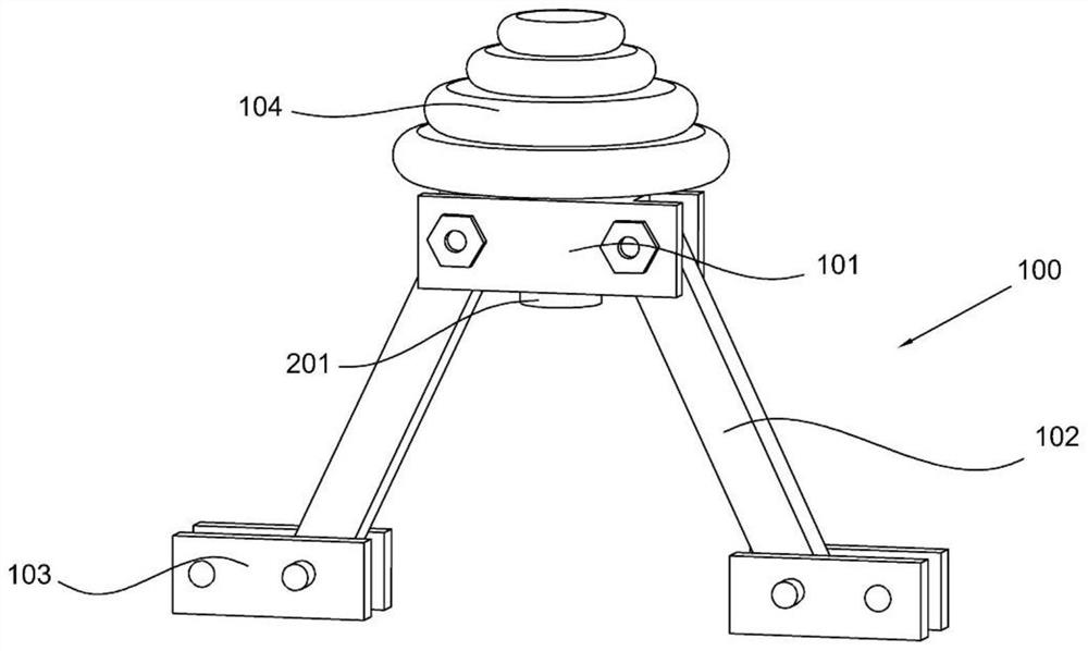
[0028] refer to Figure 1-4 , a triangular fixed post insulator, including a bracket main body 100. In this embodiment, the bracket main body 100 is a component arranged on a cross arm for support. The bracket main body 100 includes an intermediate block 101 connected with an insulator 104, The middle block 101 is block-shaped in shape, made of stainless steel or alloy steel, and its own hardness is relatively large. The two ends of the middle block 101 are also rotatably connected with support rods 102. There are two support rods 102, and the rotation of the support rods 102 The plane is a vertical plane, and a foot piece 103 is also hinged at the lower end of the support rod 102, and the foot piece 103 is threadedly connected with the cross arm.

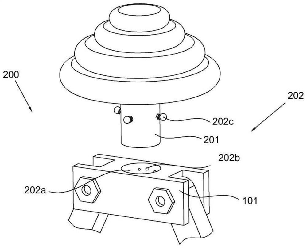
[0029] Further, the present invention also includes a mounting assembly 200. In this embodiment, the mounting assembly 200 includes a connecting rod 201 slidably connected to the middle block 101 and a locking member 202 arranged o...


PUM

PropertyMeasurementUnit
angleaaaaaaaaaa

Abstract

The invention discloses a triangular fixed post insulator, which comprises a bracket main body, a middle block connected with the insulator, a bracket rod rotationally connected with the middle block and a foot block hinged to the lower end of the bracket rod, and the foot block is in threaded connection with a cross arm; the mounting assembly comprises a connecting rod connected to the middle block in a sliding manner and a locking piece arranged on the connecting rod; the adjusting assembly is arranged on the middle block, a traditional single supporting column is changed into double supporting columns, the supporting height of the insulator is reduced, and from the mechanical angle, the higher the height is, the smaller the transverse stress is, an insulator supporting column bolt is reduced to 100 mm, the insulator supporting column bolt is fixedly installed at a bolt hole in the top end of a triangular frame, and bolt connection is designed and used.

Description

technical field [0001] The invention relates to the technical field of insulators, in particular to a triangular fixed post insulator. Background technique [0002] Conventional overhead conductor lines are laid through two pillar insulators or suspension insulators, which are fixedly installed on the double cross arm and double top sleeve respectively. , it often happens that the fixing bolts of the column insulator or the fixed cross arm and double top sleeve will bend and deform with the direction of the force due to the influence of the force, the opening of the cross arm and double top sleeve will become larger, the cross arm and double top sleeve will be twisted and deformed, and the wire tension will If it is too large, it will damage the internal structure of the wire; in severe cases, it will even cause damage to the insulator and cause the line to lose its insulation protection. Direct contact with conductors such as cross-arms will cause the wire to discharge to t...

Claims


Application Information

Patent Timeline
Patent Type & Authority Applications(China)
IPC IPC(8): H01B17/14H01B17/16H02G7/05
CPCH01B17/14H01B17/16H02G7/05
Inventor 李章权陆韦刚张果李洪勾清亮吕秀郑太然刘庆国岳廷学孙胜龚红艳李书军王波江甫瑞宋健张兴云郭昌胜李德侠黄鑫宁李文冬徐建高朱江平付习平胡文娟陈飞杨贞贵
Owner GUIZHOU POWER GRID CO LTD
Why Eureka
Try Eureka