Online monitoring system for low-voltage capacitor cabinet

A monitoring system, capacitor cabinet technology, applied in electromagnetic measurement devices, electric/magnetic solid deformation measurement, electric/magnetic profile/curvature measurement, etc., can solve problems such as misjudgment, partial discharge, and capacitor terminal voltage rise, etc. Achieve the effect of improving work efficiency, ensuring stability, and solving limitations

Pending Publication Date: 2022-03-01
GUANGDONG POWER GRID CO LTD +1
View PDF16 Cites 1 Cited by
  • Summary
  • Abstract
  • Description
  • Claims
  • Application Information

AI Technical Summary

Problems solved by technology

In particular, the wide application of various switching electronic devices now leads to the increase of harmonics in the power grid. When the capacitor operates in a grid containing harmonics, the current flowing into the power capacitor will increase with the increase of the harmonic current, while The harmonic current passing through the power capacitor will cause the voltage of the capacitor terminals to rise. When the voltage between the terminals is high enough, it will cause partial discharge and aggravate the dielectric aging of the power capacitor, thus affecting the service life of the power capacitor.
[0004] On-line monitoring technology is an emerging technology field that has developed rapidly in recent years. However, most of the existing on-line monitoring and fault diagnosis systems for capacitors judge the working status of capacitors by monitoring a certain characteristic data of the capacitor or through the relevant experience of the staff. , this monitoring and diagnosis method has certain limitations. Manual detection usually relies on the relevant experience of the staff, and judging the operating state of the capacitor through a single characteristic data is likely to cause misjudgment

Method used


Image

  • Online monitoring system for low-voltage capacitor cabinet
  • Online monitoring system for low-voltage capacitor cabinet
  • Online monitoring system for low-voltage capacitor cabinet

Examples


Embodiment Construction

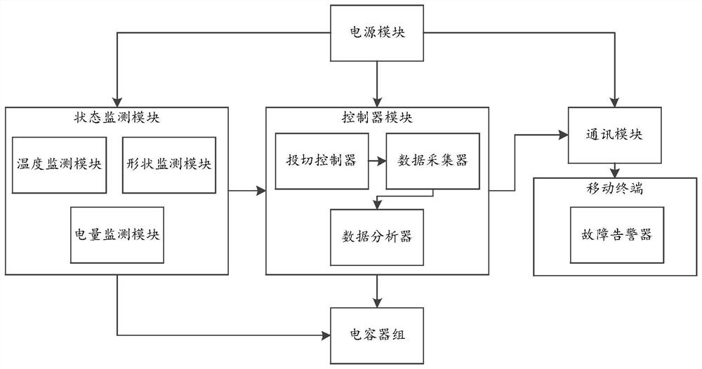
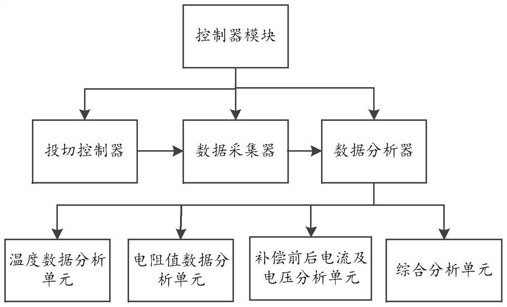
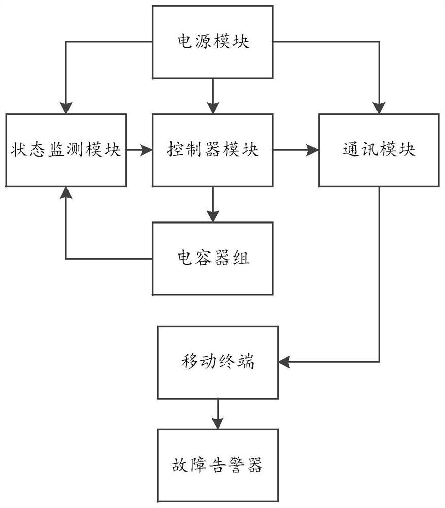
[0045]An embodiment of the present invention provides an online monitoring system for a low-voltage capacitor cabinet, which is used to solve the technical problem that the traditional detection technology uses manual or single performance to detect the working state and performance of the capacitor, which makes the detection have limitations.

[0046] In order to make the purpose, features and advantages of the present invention more obvious and understandable, the technical solutions in the embodiments of the present invention will be clearly and completely described below in conjunction with the accompanying drawings in the embodiments of the present invention. Obviously, the following The described embodiments are only some, not all, embodiments of the present invention. Based on the embodiments of the present invention, all other embodiments obtained by persons of ordinary skill in the art without making creative efforts belong to the protection scope of the present invent...


PUM


Abstract

The invention discloses a low-voltage capacitor cabinet on-line monitoring system, which is applied to a low-voltage capacitor cabinet, the low-voltage capacitor cabinet comprises a plurality of capacitors, and the system comprises a state monitoring module, a controller module, a communication module, a mobile terminal and a power supply module. The state monitoring module is used for monitoring the state change of the capacitor and acquiring state data; the controller module is used for collecting and analyzing capacitor operation data and outputting an analysis result; the communication module is used for receiving the capacitor analysis result sent by the controller module; the mobile terminal is used for receiving the capacitor analysis result sent by the communication module and carrying out fault judgment on the capacitor; the power supply module is used for supplying power to the state monitoring module, the controller module and the communication module; the system monitors a plurality of state quantities in the operation process of the capacitor, so that the operation state of the capacitor is accurately and quickly judged.

Description

technical field [0001] The invention relates to the field of on-line monitoring of electrical equipment faults, in particular to an on-line monitoring system for a low-voltage capacitor cabinet. Background technique [0002] In the current power system, most of the electric loads are inductive loads. Such loads will reduce the power factor of the power grid. The lower power factor not only reduces the utilization rate of power distribution equipment, but also increases the investment in power supply. Voltage quality reduces equipment life and greatly increases line losses. Through the extensive access to the capacitor compensation cabinet in the power distribution system, it is used to balance the inductive load, improve the system power factor and the quality of the power supply. so. [0003] Capacitance compensation cabinets are widely used in various power distribution places. The core components in capacitor compensation cabinets are capacitors. The service life of cap...

Claims


Application Information

Patent Timeline
Patent Type & Authority Applications(China)
IPC IPC(8): G01R31/00G01B7/28G01B7/16G01K13/00
CPCG01R31/00G01B7/28G01B7/18G01K13/00
Inventor 李锦焙袁红波傅子明王圣何显辉谢湘昭梁梓洋黄铭灏
Owner GUANGDONG POWER GRID CO LTD
Why Eureka
Try Eureka