
Micro pressure optical measurement method and calibration device

A calibration device and pressure testing technology, which is applied to measuring devices, fluid pressure measurement using optical methods, measuring fluid pressure, etc., can solve problems such as the difficulty of accurate measurement of micro pressure and the contradiction of dynamic response, so as to achieve accurate measurement and calibration, and improve Sensitivity and precision, and the effect of increasing the optical path length

Pending Publication Date: 2022-03-01
BEIJING CHANGCHENG INST OF METROLOGY & MEASUREMENT AVIATION IND CORP OF CHINA
View PDF2 Cites 0 Cited by
  • Summary
  • Abstract
  • Description
  • Claims
  • Application Information

AI Technical Summary

Problems solved by technology

[0003] In order to solve the problem of difficult accurate measurement of micro pressure caused by the contradiction between cavity length and pressure stability and dynamic response in the current optical pressure measurement, the purpose of the present invention is to provide an optical measurement method and calibration device for micro pressure, which can realize small space Optical micro-pressure high-precision measurement and micro-pressure calibration in the environment improve the sensitivity and accuracy of pressure measurement

Method used


Image

  • Micro pressure optical measurement method and calibration device
  • Micro pressure optical measurement method and calibration device
  • Micro pressure optical measurement method and calibration device

Examples


Embodiment Construction

[0032] The present invention is further detailed in connection with the accompanying drawings and examples. In this embodiment, the present invention is predicted, and a specific embodiment is given, but the scope of the invention is not limited to the following examples.

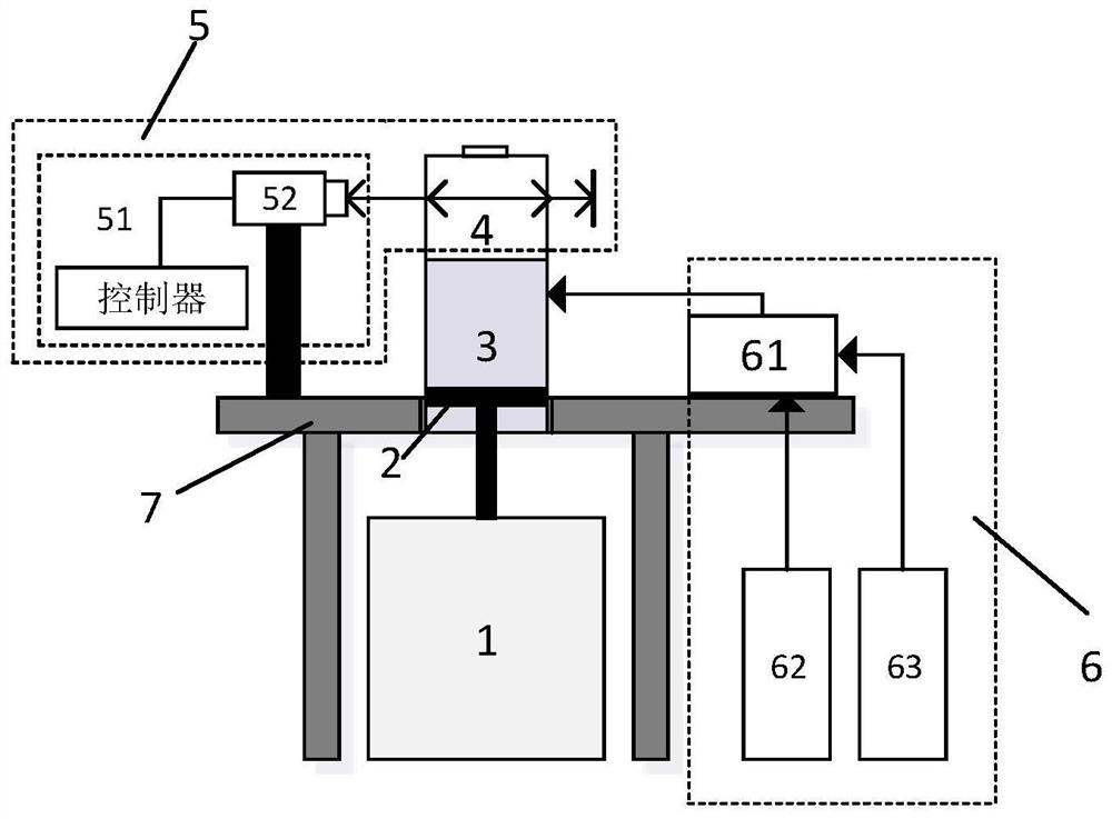
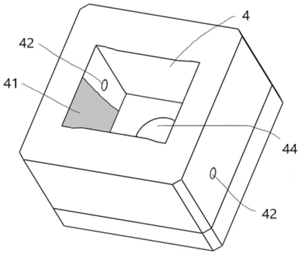
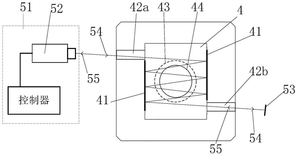
[0033] Such as figure 1 As shown, the microphilic optical measuring device disclosed herein is mainly composed of a vibration table 1, a piston 2, a variable barrier mechanism 3, a pressure test chamber 4, a laser interference measuring system 5, and a control system 6;

[0034] The pressure test chamber 4 is connected to the variable barrier mechanism 3, inner communication, the vibration table 1 is connected to the piston 2 rod, the piston 2 is in-depth variable barrier mechanism 3, and the pressure regulating mechanism 61 is connected to the vapor volume 3 for debugging volume mechanism 3. Static initial pressure. The vibrating table 1 motion drive variable allerge mechanism 3 changes its inner pressure cham...


PUM


Abstract

The invention discloses a micro pressure optical measurement method and a calibration device, and belongs to the technical field of metering and testing. The device is mainly composed of a vibration table, a piston, a variable volume mechanism, a pressure test cavity, a laser interference measurement system and a control system. The pressure testing cavity is connected with the variable volume mechanism, the vibration table is connected with the piston rod, the piston rod goes deep into the variable volume mechanism, and the vibration table moves to drive the variable volume mechanism to change the volume of a pressure cavity in the variable volume mechanism and simultaneously drive the pressure in the pressure testing cavity to change. A laser interference optical system is used for realizing high-precision traceability of micro pressure, a plurality of high-reflection surfaces are arranged in a pressure test cavity, and the contradiction among the cavity length size, pressure stability and dynamic response is solved by reflecting incident light for multiple times, increasing a laser transmission path in the cavity and increasing a measurement optical path in a small-size pressure cavity; the sensitivity and precision of pressure measurement are improved, and precise measurement and calibration of tiny static or dynamic pressure can be realized.

Description

Technical field [0001] The present invention relates to a small pressure optical measurement method and a calibration device belong to the field of metering test. Background technique [0002] Pressure is one of the important parameters of mechanical measuring and testing, which is very wide in the fields of aviation, aerospace, nuclear industry, ship, weapons. During the national defense industrial test, the accuracy of the pressure value directly affects the security and development of all fields of defense industries. In order to improve the accuracy of the pressure meter, people make full use of high-precision, high-resolution, high dynamic characteristics such as optical measurements such as laser interference, and use optical measurement means for pressure measurement, and improve the pressure measurement accuracy, and is expected Establish a higher precision pressure standard and dynamic pressure standard. Among them, the optical pressure measurement based on the refractiv...

Claims


Application Information

Patent Timeline
IPC IPC(8): G01L11/02G01L27/00
CPCG01L11/02G01L27/002
Inventor 谢兴娟杨军李博田森
Owner BEIJING CHANGCHENG INST OF METROLOGY & MEASUREMENT AVIATION IND CORP OF CHINA
Learn More