Ultra-large circulating fluidized bed boiler
A circulating fluidized bed, ultra-large technology, applied in the direction of fluidized bed combustion equipment, combustion type, fuel burned in the molten state, etc., can solve the problem of large-scale development of high parameters of circulating fluidized bed boilers, tail flue gas Problems such as excessive deviation and difficult maintenance of the heating surface of the inner ring achieve the effects of strong secondary air penetration, small footprint, and appropriate cross-sectional width-to-depth ratio
- Summary
- Abstract
- Description
- Claims
- Application Information
AI Technical Summary
Problems solved by technology
Method used
Image
Examples
Embodiment 1
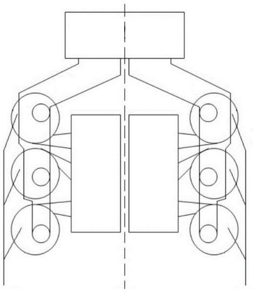
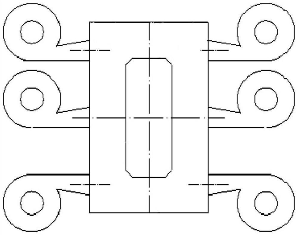
[0031] Such as image 3 and 4 As shown, a 1000MW ultra-large circulating fluidized bed boiler includes a furnace 1 composed of a membrane water-cooled wall and a cyclone separator 2. The furnace 1 is composed of interconnected front furnaces and left and right furnaces. U-shaped structure, that is, the cross-section of the furnace is U-shaped, and the left and right furnaces are arranged symmetrically with respect to the axial center line of the boiler. Inside the furnace, the cyclone separator 2 is arranged in the middle area of the U-shaped furnace 1 and is connected to the furnace 1 through the flue. The boiler occupies a small area, and the inside of the furnace, the separator, and the feeder are all convenient for maintenance.
[0032] In this embodiment, the length AB of the left side of the U-shaped furnace 1, the length BC of the front side and the length CD of the right side of the furnace are 1:1:1, and the widths of the three sides of the U-shaped furnace 1 are e...
Embodiment 2
[0039] This embodiment is basically the same as Embodiment 1, the main difference is: as Figure 5 and 6 As shown, when the depth of the furnace is small and the width is large, the two cyclone separators near the front furnace are connected to the front furnace through independent flues, and the other cyclones are connected to the left and right furnaces through independent flues. connected. Among them, the cyclone separator body has the same structural parameters, and the left and right cyclone separator groups are arranged symmetrically. Due to the small depth of the furnace, in order to arrange a sufficient number of superheaters and reheaters, an external heat exchanger is installed at the bottom of the cyclone separator. Device 6, the tail wall adopts a single flue structure.
Embodiment 3
[0041] This embodiment is basically the same as Embodiment 2, the main difference is: as Figure 7 As shown, the bending angle α formed between the left and right sides of the U-shaped furnace and the front side furnace is between 90° and 180°, and the cyclone separator is arranged along the bending direction of the left and right sides of the furnace. .
PUM
 Abstract
Description
Claims
Application Information
 - R&D
- Intellectual Property
- Life Sciences
- Materials
- Tech Scout
- Unparalleled Data Quality
- Higher Quality Content
- 60% Fewer Hallucinations
Browse by: Latest US Patents, China's latest patents, Technical Efficacy Thesaurus, Application Domain, Technology Topic, Popular Technical Reports.
© 2025 PatSnap. All rights reserved.Legal|Privacy policy|Modern Slavery Act Transparency Statement|Sitemap|About US| Contact US: help@patsnap.com


