
Light guide assembly

A technology of light guide components and light guide sheets, which is applied in the field of light guides, and can solve problems such as the inability to achieve uniform light emission, color cast, and lack of illumination of light guide strips

Pending Publication Date: 2022-02-25
深圳市兆驰数码科技股份有限公司
View PDF0 Cites 0 Cited by
  • Summary
  • Abstract
  • Description
  • Claims
  • Application Information

AI Technical Summary

Problems solved by technology

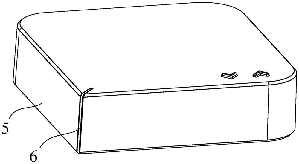
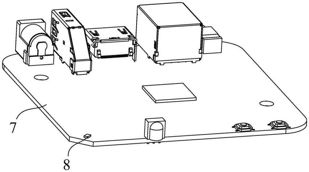
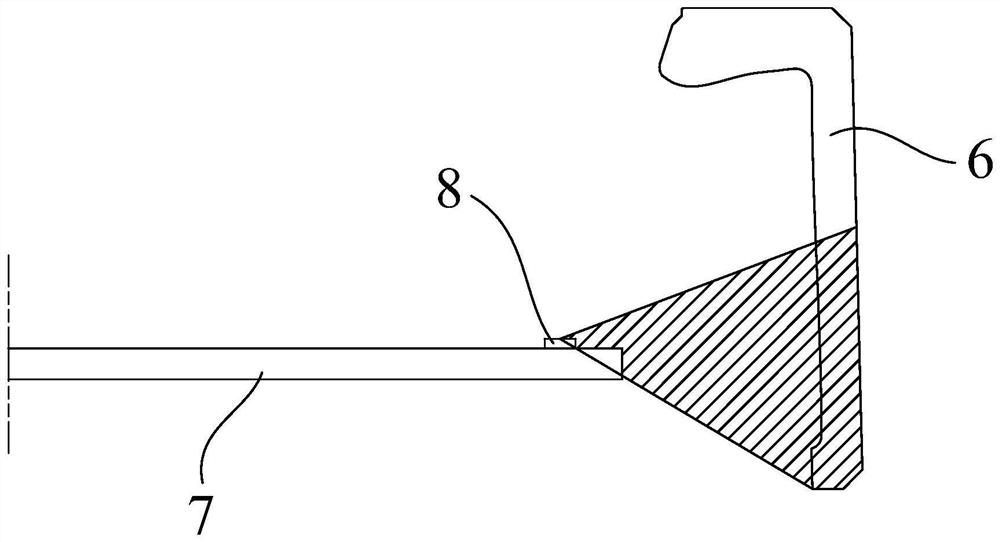
[0002] In the existing technology, such as Figure 1 to Figure 3 As shown, an L-shaped light guide is embedded on the corner of the housing. Since the PCBA is located inside the housing, the partial shadow position of the L-shaped light guide shown is not within the direct range of the LED, that is, the position of the L-shaped light guide The lower end cannot be irradiated with light; the light guide strip cannot be evenly illuminated; moreover, since the RBG LED is composed of three primary color lights, when the three primary color light passes through the medium of the light guide strip, if dispersion occurs, it may appear on the light emitting surface Local color cast phenomenon appears on the surface, especially the effect of white light will be more obvious; so it is necessary to solve these problems

Method used


Image

  • Light guide assembly
  • Light guide assembly
  • Light guide assembly

Examples


Embodiment Construction

[0035] The principles and features of the present invention are described below in conjunction with the accompanying drawings, and the examples given are only used to explain the present invention, and are not intended to limit the scope of the present invention.

[0036] Such as Figure 4 to Figure 8 shown, where Figure 6 to Figure 8 The arrows in are the ray irradiation or reflection paths.

[0037] A light guide assembly, comprising a light guide sheet 1 and a diffuser sheet 2, the light guide sheet 1 is placed at one end of the diffuser sheet 2, and is fixedly connected to the diffuser sheet 2; The end face is provided with a first reflective layer 3 .

[0038] The LED 8 is placed at the lower end of the light guide sheet 1, and the LED emits light. When the light enters the inside of the light guide sheet 1, part of the light is irradiated to the upper end of the diffuser sheet 2 through the light guide sheet 1; part of the light is irradiated to the first reflective l...


PUM


Abstract

The invention relates to a light guide assembly. The light guide assembly comprises a light guide sheet and a light diffusion sheet; the light guide sheet is arranged at one end of the light diffusion sheet and is fixedly connected with the light diffusion sheet; and a first reflecting layer is arranged on the upper end surface of the light guide sheet. Compared with the prior art, the light scattering sheet is used for scattering the light irradiated by the light guide sheet and the light reflected by the light guide sheet, so that the light is uniformly emitted from the surface of the light scattering sheet.

Description

technical field [0001] The present invention relates to the field of light guide technology, in particular, to a light guide assembly. Background technique [0002] In the prior art, such as Figure 1 to Figure 3 As shown, an L-shaped light guide is embedded on the corner of the housing. Since the PCBA is located inside the housing, the partial shadow position of the L-shaped light guide shown is not within the direct range of the LED, that is, the position of the L-shaped light guide The lower end cannot be irradiated with light; the light guide strip cannot be evenly illuminated; moreover, since the RBG LED is composed of three primary color lights, when the three primary color light passes through the medium of the light guide strip, if dispersion occurs, it may appear on the light emitting surface Local color cast phenomenon appears on the display, especially the effect of white light will be more obvious; so it is necessary to solve these problems. Contents of the inv...

Claims


Application Information

Patent Timeline
IPC IPC(8): G02B6/00
CPCG02B6/0055G02B6/0051G02B6/0065
Inventor 杨华德李相宏谭红军
Owner 深圳市兆驰数码科技股份有限公司
Learn More