
Paper direction changing device for digital printer

A technology for printers and paper is applied in the field of paper orientation changing devices for digital printers, which can solve the problems of low printing efficiency, increased labor intensity of staff, and inability to realize automatic paper reversal.

Pending Publication Date: 2022-02-25
YUTIAN UANCHOR PACKAGING MACHINERY
View PDF0 Cites 0 Cited by
  • Summary
  • Abstract
  • Description
  • Claims
  • Application Information

AI Technical Summary

Problems solved by technology

[0003] The purpose of the present invention is to provide a paper direction changing device for digital printers, which solves the problems that the existing printing equipment cannot realize the automatic direction change of the paper, increases the labor intensity of the staff, and has low printing efficiency

Method used


Image

  • Paper direction changing device for digital printer
  • Paper direction changing device for digital printer
  • Paper direction changing device for digital printer

Examples


Embodiment Construction

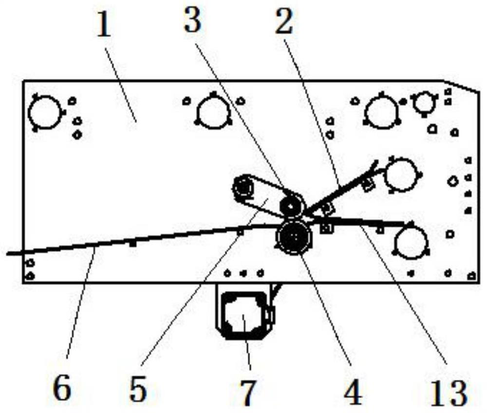
[0018] Such as Figure 1-4 As shown, a paper direction changing device for a digital printer includes a frame 1, a conveying channel 2 is arranged in the middle of the frame 1, the conveying channel 2 is arranged obliquely, and a conveying shaft is arranged at the bottom end of the conveying channel 2 4. The conveying shaft 4 is rotatably mounted on the frame 1, a driving assembly is arranged below the conveying shaft 4, and a platen shaft 3 is arranged above the conveying shaft 4, and the platen shaft 3 A pendulum 5 is provided on both sides, and the platen shaft 3 is rotatably mounted on the pendulum 5 through a bearing 16 , and the end of the pendulum 5 away from the paper platen 3 is rotatably connected by a fixed pin 14 On the frame 1, a passage for paper to pass is provided between the platen shaft 3 and the conveying shaft 4, a paper guide plate 6 is provided on the left side of the passage, and a paper guide plate 6 is provided on the right side of the conveying shaft ...


PUM


Abstract

The invention discloses a paper direction changing device for a digital printer. The device comprises a rack, a conveying channel is arranged in the middle of the rack, the conveying channel is obliquely arranged, a conveying shaft is arranged at the bottom end of the conveying channel, the conveying shaft is rotationally installed on the rack, a driving assembly is arranged below the conveying shaft, a paper pressing shaft is arranged above the conveying shaft, swing frames are arranged on the two sides of the paper pressing shaft, the paper pressing shaft is rotationally installed on the swing frames through bearings, the ends, away from the paper pressing shaft, of the swing frames are rotationally connected to the rack through fixing pin shafts, a channel for paper to pass through is arranged between the paper pressing shaft and the conveying shaft, a paper guide plate is arranged on the left side of the channel, and a second conveying channel is arranged on the right side of the conveying shaft. Paper is output through the first conveying channel, a servo motor drives the conveying shaft to rotate forwards, the servo motor controls the conveying shaft to rotate reversely after the paper moves leftwards to reach a designated position, the paper is turned around, and the paper moves rightwards to be continuously conveyed through the second conveying channel.

Description

technical field [0001] The invention relates to the technical field of printing equipment, in particular to a paper direction changing device for a digital printer. Background technique [0002] When the existing printer is working, the paper can only move in the same direction after entering the printer, and the paper cannot be automatically reversed. If double-sided printing is required, the paper needs to be manually reversed, which increases the labor intensity of the staff and reduces the printing efficiency. . Contents of the invention [0003] The purpose of the present invention is to provide a paper direction changing device for a digital printer, which solves the problems that existing printing equipment cannot realize automatic paper direction change, increases the labor intensity of workers, and has low printing efficiency. [0004] In order to solve the problems of the technologies described above, the present invention adopts the following technical solution...

Claims


Application Information

Patent Timeline
IPC IPC(8): B65H5/36B65H5/06B65H29/20B65H29/52
CPCB65H5/36B65H5/062B65H29/20B65H29/52B65H2701/10B65H2801/15
Inventor 林笑安杨东波林兆江邱志国
Owner YUTIAN UANCHOR PACKAGING MACHINERY
Learn More