
Pipeline measuring method and device

A measurement method and pipeline technology, applied in image data processing, instruments, calculations, etc., can solve the problems of inability to meet the measurement requirements of long pipelines, the impact of measurement accuracy detection accuracy, and high technical difficulty requirements, to solve the phenomenon of mismatching, The effect of reducing blind spots and large field of view

Pending Publication Date: 2022-02-18
新拓三维技术(深圳)有限公司
View PDF0 Cites 0 Cited by
  • Summary
  • Abstract
  • Description
  • Claims
  • Application Information

AI Technical Summary

Problems solved by technology

Due to the long measurement time and high technical difficulty requirements of this measurement method, it can only be applied to occasions where the instrument can touch the measurement scene, and cannot meet the measurement requirements of long pipelines.
[0004] As a typical representative of the active vision method of non-contact measurement, structured light scanning can divide and extract the characteristic area of ​​the image by projecting modulated laser light or speckle on the surface of the object, and the industrial camera collects the pipeline with the characteristic image on the surface. , stitching point clouds to realize pipeline reconstruction, although compared with three-coordinate measurement, the measurement time is significantly shortened, but the measurement accuracy is easily affected by the equipment detection accuracy

Method used


Image

  • Pipeline measuring method and device
  • Pipeline measuring method and device
  • Pipeline measuring method and device

Examples


Embodiment Construction

[0045] The present invention will be further described in detail below in conjunction with the accompanying drawings and embodiments. It should be understood that the specific embodiments described here are only used to explain the present invention, but not to limit the present invention. In addition, it should be noted that, for the convenience of description, only some structures related to the present invention are shown in the drawings but not all structures.

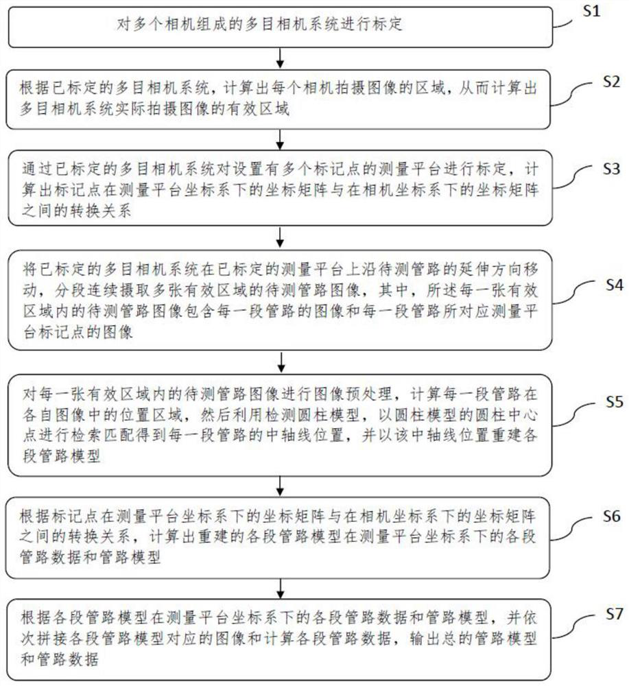
[0046] figure 1 It is a schematic flowchart of a pipeline measurement method provided according to an embodiment of the present invention, and the pipeline measurement method includes the following steps:

[0047] S1. Calibrate the multi-eye camera system composed of multiple cameras;

[0048] S2. According to the calibrated multi-camera system, calculate the area of ​​the image captured by each camera, so as to calculate the effective area of ​​the image actually captured by the multi-camera system;

[0049] S3...


PUM


Abstract

The invention discloses a pipeline measurement method and device. The method comprises the steps: calibrating a multi-view camera system and a measurement platform; calculating an effective region of an image actually shot by the multi-view camera system; meanwhile, calculating the conversion relation between the coordinate matrix of the mark point under the coordinate system of the measuring platform and the coordinate matrix of the mark point under the coordinate system of the camera; moving the calibrated multi-view camera system on the calibrated measuring platform in the extending direction of the pipeline to be measured; continuously shooting a plurality of to-be-detected pipeline images in effective areas in a segmented mode; then performing image preprocessing; calculating the position area of each pipeline section in the corresponding image; by using a detection cylinder model, performing retrieval matching through the cylinder center point of the cylinder model to obtain the central axis position of each pipeline section; reconstructing a model of each section of pipeline according to the position of the central axis; splicing images corresponding to sections of the pipeline model and calculating data of each section of pipeline after coordinate transformation; and outputting a total pipeline model and pipeline data.

Description

technical field [0001] The invention relates to the field of pipeline measurement, in particular to a pipeline measurement method and a device thereof. Background technique [0002] As a structure that can transport materials and connect, pipelines are widely used in automobiles, ships, aerospace and other fields. And because of its wide range of scenarios, the detection of pipelines has become a popular research direction in recent years. Due to the different sizes of pipelines, it also poses a lot of challenges to the detection methods. At present, most of the measurement methods are aimed at the pipe fittings whose length is within 2m, and there is still no good solution for the measurement of pipe fittings beyond the 2m range. [0003] The measurement of pipelines can be divided into two types: contact type and non-contact type according to the implementation method. At present, the most widely used and most accurate contact type measurement is three-coordinate measure...

Claims


Application Information

Patent Timeline
IPC IPC(8): G06T7/00G06T7/13G06T7/80
CPCG06T7/0004G06T7/13G06T7/85G06T2207/10004G06T2207/30244
Inventor 唐正宗李磊刚庞然
Owner 新拓三维技术(深圳)有限公司
Learn More