
Inclined shaft heading machine

A technology for roadheaders and inclined shafts, which can be used in mining equipment, earthwork drilling, tunnels, etc. It can solve the problems of difficult installation of steel arch frames at the bottom of tunnels, and achieve the effect of improving splicing efficiency and shortening distances

Pending Publication Date: 2022-02-18
CHINA RAILWAY ENGINEERING EQUIPMENT GROUP CO LTD
View PDF3 Cites 0 Cited by
  • Summary
  • Abstract
  • Description
  • Claims
  • Application Information

AI Technical Summary

Problems solved by technology

[0004] The purpose of the present invention is to provide an inclined shaft boring machine to solve the technical problem of difficult installation of the steel arch frame at the bottom of the tunnel when the boring machine is driving in the prior art

Method used


Image

  • Inclined shaft heading machine
  • Inclined shaft heading machine
  • Inclined shaft heading machine

Examples


Embodiment 1

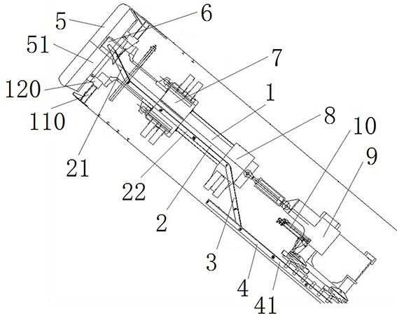
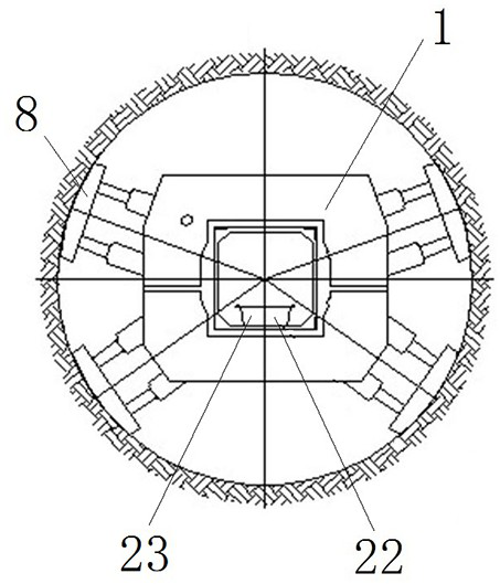
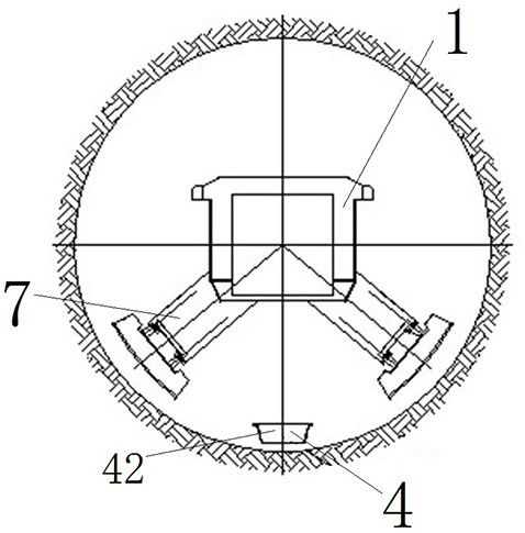
[0036] Such as figure 1 As shown, the inclined shaft boring machine includes a main beam 1, which extends along the direction of the inclined shaft tunnel. The front end of the main beam 1 is connected to the cutter head 5 through the cutter head flange 120, and the cutter head 5 is provided with a muck bin 51. The rear side of the muck bin 51 is provided with a slag collecting tank 6, which is connected with the main beam 1 for collecting the muck in the muck bin 51; The inclined shaft boring machine moves forward along the axial direction of the tunnel; the rear support 8 is installed at the end of the main beam 1 for supporting the main beam 1 when the stay shoe 7 is retracted; the main drive 110 and the slide are also installed on the main beam 1 For the slag parts, the main drive 110 drives the cutter head 5 to move, and the slag sliding parts are connected with the slag collecting tank 6;

[0037] Main girder 1, cutter head 5, support shoe 7, rear support 8 and anti-rol...

Embodiment 2

[0047] The difference between this embodiment and Embodiment 1 is that in Embodiment 1, the central slag slider 2 is fixedly connected to the transfer slag slider 3 . And in the present embodiment, the transfer slag sliding part is swingably connected with the central slag sliding part.

Embodiment 3

[0049] The difference between this embodiment and Embodiment 1 lies in that in Embodiment 1, the slag slag runner has a groove-like structure as a whole. In the present embodiment, the center slag chute and the transfer slag chute in the slag chute are tubular structures, and the ends of the tubular transfer slag chute extend into the bottom slag chute of the bottom slag chute.


PUM


Abstract

The invention discloses an inclined shaft heading machine. The inclined shaft heading machine comprises a main beam and a cutterhead, wherein the cutterhead is connected to a front end of the main beam, and a muck bin is arranged on the rear side of the cutterhead; the inclined shaft heading machine further comprises a main drive installed on the main beam, the inclined shaft heading machine further comprises a residue collecting groove which is installed on the main beam and used for collecting residue soil in the residue soil bin, and the residue collecting groove is located in the middle of the residue soil bin; the inclined shaft heading machine further comprises a center slag sliding part and a bottom slag sliding part, the center slag sliding part is installed on the main beam, the bottom slag sliding part is used for being fixed to the bottom of a tunnel, and the bottom slag sliding part comprises at least two slag sliding splicing joints; a transferring slag sliding part is arranged between the center slag sliding part and the bottom slag sliding part, one end of the transferring slag sliding part is connected with the center slag sliding part, and the other end of the transferring slag sliding part slides in the bottom slag sliding part in a guiding mode so that slag in the center slag sliding part can be transferred to the bottom slag sliding part; when the bottom of the transferring slag sliding part slides to a front end of the bottom slag sliding part, the front end of the bottom slag sliding part can be additionally provided with a slag sliding splicing section for the transferring slag sliding part to slide in.

Description

technical field [0001] The invention relates to the field of roadheaders, in particular to an inclined shaft roadheader. Background technique [0002] The slagging of the roadheader in the prior art usually adopts two modes of center slag discharge and bottom slag discharge. The roadheader with the center slag discharge is the slag discharge method disclosed in the patent document with the application publication number CN111963185A, and the bottom slag discharge roadheader As the application publication number is the slagging method disclosed in the patent literature of CN113107515A. [0003] For inclined shafts, bottom slag removal is generally adopted, such as the slag removal method disclosed in a tunnel inclined shaft construction system and construction method disclosed in the patent document CN112412478A, but when adopting bottom slag removal, the slag removal The chute is laid at the bottom of the tunnel. When installing the steel arch at the bottom of the tunnel, t...

Claims


Application Information

Patent Timeline
Patent Type & Authority Applications(China)
IPC IPC(8): E21D9/12E21D9/11E21D9/02
CPCE21D9/12E21D9/11E21D9/02
Inventor 贾连辉于庆增宁向可贺开伟马超高翔范书恒张啸
Owner CHINA RAILWAY ENGINEERING EQUIPMENT GROUP CO LTD
Learn More