
Gear convenient to disassemble and assemble and used for mechanical equipment

A technology of mechanical equipment and gears, applied in mechanical equipment, portable lifting devices, belts/chains/gears, etc., can solve the problems of inconvenient disassembly and assembly, dust entering the joint, pollution or erosion of the joint, etc. Easy to install and reduce pollution

Pending Publication Date: 2022-02-15
昆山辰聚泽精密齿轮制造有限公司
View PDF1 Cites 0 Cited by
  • Summary
  • Abstract
  • Description
  • Claims
  • Application Information

AI Technical Summary

Problems solved by technology

The present invention achieves the goal of structural stability by providing the main gear and the locking block. The operator places the main gear on the support rod. Tight block, and the inside of the locking block has anti-skid work, which fills the structural gap between the two to the greatest extent. At the same time, the main gear and the locking block adopt the clamping form of the triangular groove and the triangular strip, and the structure is stable. Good," but the gear is not easy to disassemble and assemble, and it will cause trouble to the staff when disassembling it
[0005] 2. The traditional gear sealing effect is not good, it is easy to cause dust to enter the connection, causing pollution or erosion to the connection, which will affect the use of the gear

Method used


Image

  • Gear convenient to disassemble and assemble and used for mechanical equipment
  • Gear convenient to disassemble and assemble and used for mechanical equipment
  • Gear convenient to disassemble and assemble and used for mechanical equipment

Examples


Embodiment 1

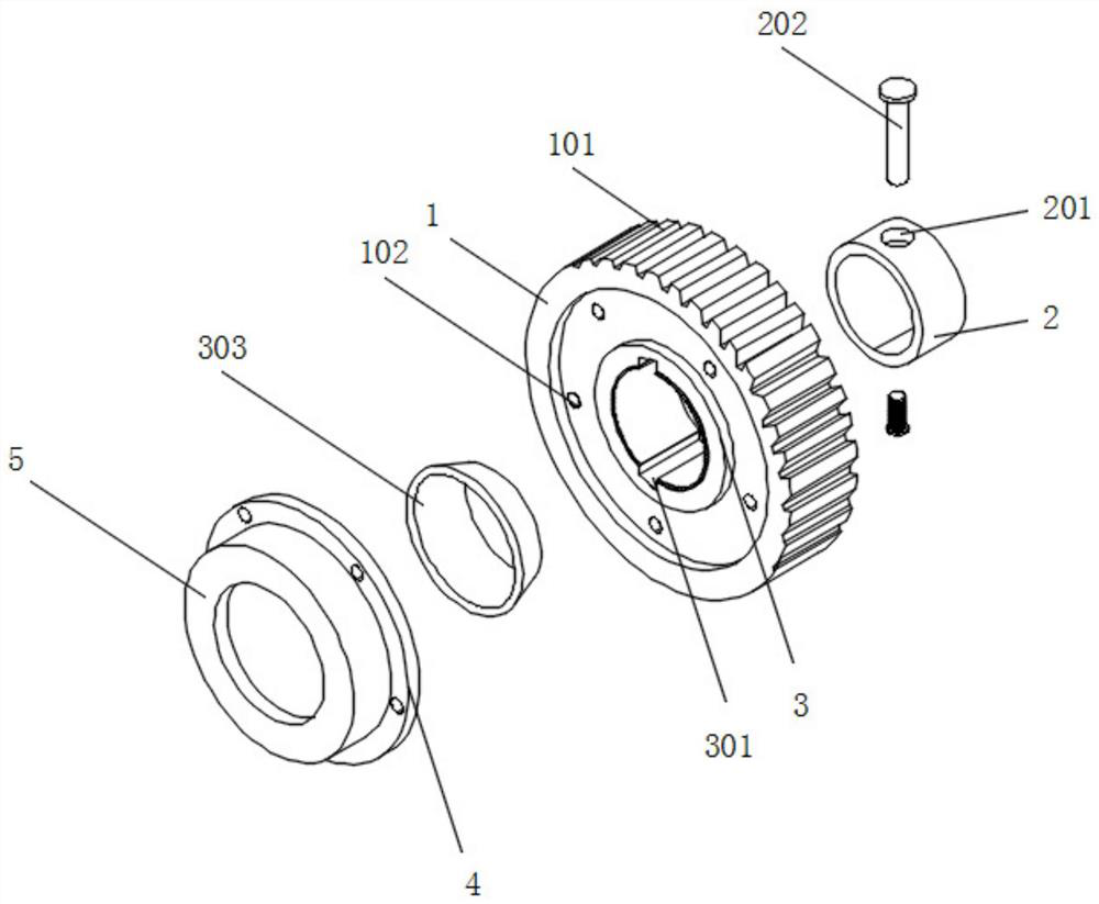
[0027] Embodiment 1 includes a gear body 1 and a fixed shaft 2. The fixed shaft 2 is installed on the back of the gear body 1. Several teeth 101 are installed on the outside of the gear body 1. The front of the gear body 1 is symmetrically provided with a first installation hole. 102. The gear body 1 is a part used for transmission. The teeth 101 provided on the outside of the gear mesh with each other to play the role of transmission. There are many types of gears, and the shapes of the gears are different. The resulting use effect It is also different, the teeth 101 play the role of connection, the top and bottom of the fixed shaft 2 are symmetrically provided with a fixed hole 201, and the inner side of the fixed hole 201 is installed with a fixed pin 202, and the fixed shaft 2 provides space for the opening of the fixed hole 201 , to provide tail vertebrae for the fixing of the gear during installation, the fixing hole 201 provides space for the fixing of the gear, and the ...

Embodiment 2

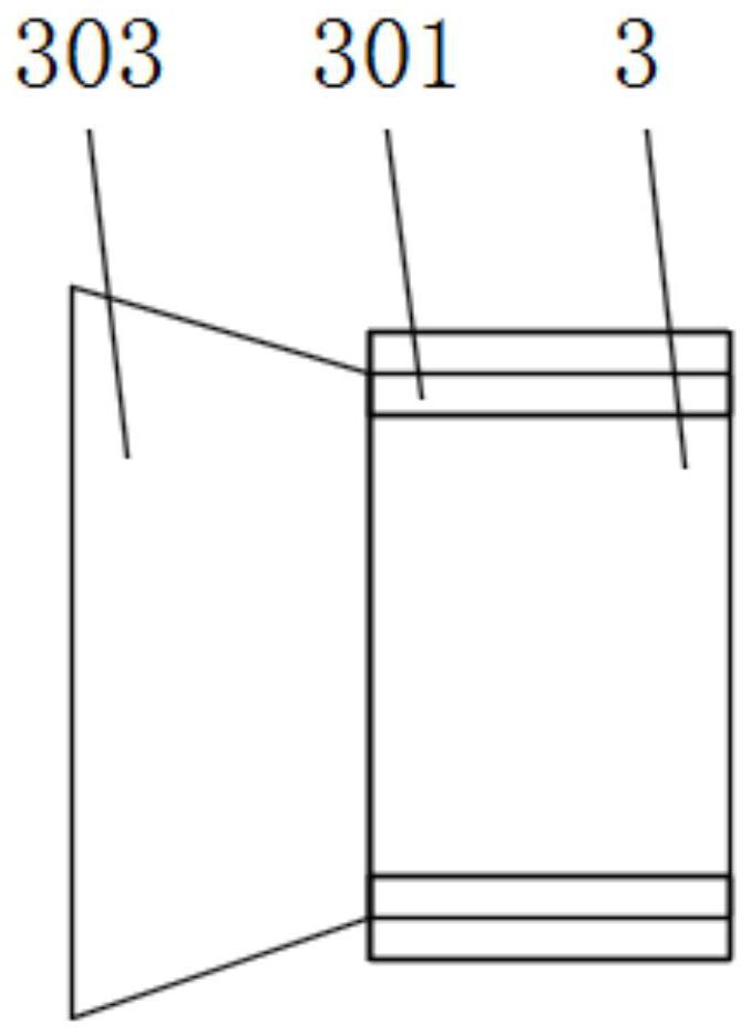
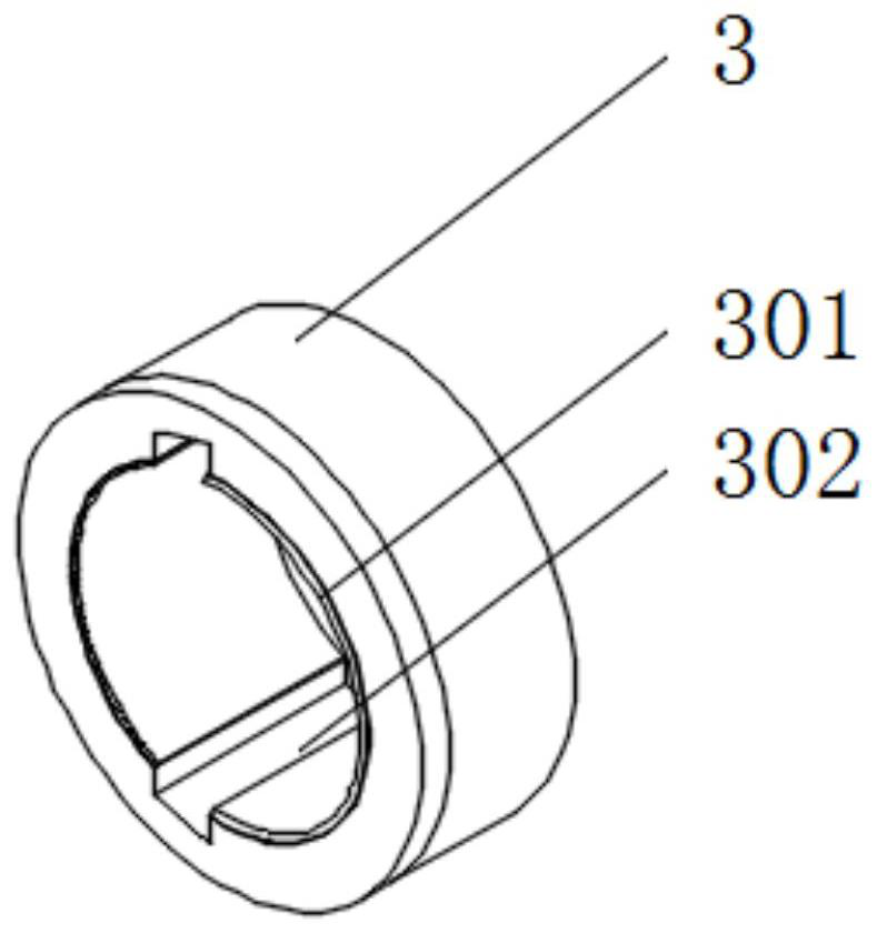
[0029] The second embodiment includes the installation shaft 3, the inside of the gear body 1 is installed with the installation shaft 3, the inner side of the installation shaft 3 is installed with a dismounting pad 302, and the top and bottom insides of the installation shaft 3 are individually and symmetrically provided with fixing grooves 301, and fixed The groove 301 is located on one side of the removal pad 302, and the front of the installation shaft 3 is installed with an installation sleeve 303. The installation shaft 3 plays a role of connection, so that the gear body 1 can be installed, and provides a function for the installation of the gear body 1, passing through the removal pad 302 to make the gear body 1 more convenient for disassembly and assembly. The inside of the installed rod and the installation shaft 3 can be prevented from rusting through the dismounting pad 302, making it difficult for the gear to be disassembled. The gear body 1 can be made It is conve...

Embodiment 3

[0031] Embodiment 3, including installation, 4 and sealing cover 5, the front of the gear body 1 is installed with a mounting part 4, and the front of the mounting part 4 is symmetrically provided with a plurality of second mounting holes 401, and the second mounting holes 401 are connected with the first mounting The holes 102 correspond to each other, and the mounting part 4 plays the role of installation, which is the installation passage position of the sealing cover 5, and enables the second mounting hole 401 to be opened at the same time, and the second mounting hole 401 provides space for the fixing of the mounting part 4, and the mounting part 4 is equipped with a sealing cover 5 on the front of the sealing cover 5, and a through hole 501 is provided on the front of the sealing cover 5. The sealing cover 5 plays a role of sealing and can prevent dust from entering the inner connection of the installation shaft 3. There are through holes 501, and the through holes 501 ar...


PUM


Abstract

The invention discloses a gear convenient to disassemble and assemble and used for mechanical equipment. The gear comprises a gear body, a mounting shaft and a mounting piece, wherein a fixing shaft is mounted on the back surface of the gear body, the mounting shaft is mounted in the gear body in a penetrating mode, a dismounting pad is mounted on the inner side of the mounting shaft, the mounting piece is mounted on the front surface of the gear body, and a sealing cover is mounted on the front surface of the mounting piece. According to the invention, the dismounting pad is mounted on the inner side of the mounting shaft, the fixing grooves are further symmetrically formed in the mounting shaft while the mounting sleeve is mounted on the front surface of the mounting shaft, when the gear needs to be mounted, the mounting rod enters the mounting shaft from the mounting sleeve, and the fixing buttons used on the two sides of the mounting rod are embedded into the inner sides of the fixing grooves, so that when the gear is mounted, the gear can be accurately mounted, the limiting effect is achieved, a worker can conveniently mount the gear, and the gear is more convenient to disassemble and assemble through the disassembling pad.

Description

technical field [0001] The invention relates to the technical field of gears, in particular to a gear for mechanical equipment that is easy to assemble and disassemble. Background technique [0002] A gear is a part used for transmission. The teeth on the outside of the gear mesh with each other to play a role in transmission. There are many types of gears, and the shapes of the gears are different, and the effects of use are also different. [0003] The defective that existing gear exists is: [0004] 1. Patent document CN214007967U discloses a special-shaped mechanical gear part for equipment transmission, "The present invention belongs to the technical field of mechanical parts, and discloses a special-shaped mechanical gear part for equipment transmission, including a main gear, the main gear The top is movably clamped with a locking block, and the bottom of the main gear is movably clamped with a backing ring, and the peripheral thread at the bottom of the main gear is...

Claims


Application Information

Patent Timeline
IPC IPC(8): F16H55/17F16H57/00F16D1/08F16J15/52
CPCF16H55/17F16H57/0025F16D1/0894F16J15/52
Inventor 郭江涛
Owner 昆山辰聚泽精密齿轮制造有限公司
Learn More