Conveyor belt device for steel belt machining

A conveyor belt and steel belt technology, which is applied in the direction of conveyor objects, transportation and packaging, rollers, etc., can solve the problem that the conveyor belt device cannot be used to convey steel plates of various specifications

Active Publication Date: 2022-02-11
ZHAOQING HONGWANG METAL IND
View PDF4 Cites 0 Cited by
  • Summary
  • Abstract
  • Description
  • Claims
  • Application Information

AI Technical Summary

Problems solved by technology

When a variety of steel plates need to be transported at the same time or at intervals to different stations, the existing conveyor belt device cannot be used to transport steel plates of various specifications

Method used


Image

  • Conveyor belt device for steel belt machining
  • Conveyor belt device for steel belt machining
  • Conveyor belt device for steel belt machining

Examples


Embodiment Construction

[0018] The specific implementation manners of the present invention will be described in further detail below in conjunction with the accompanying drawings. It should be understood that the specific embodiments described here are only used to illustrate and explain the present invention, and are not intended to limit the present invention.

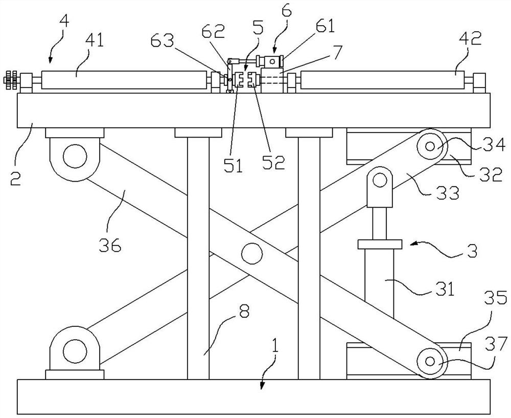
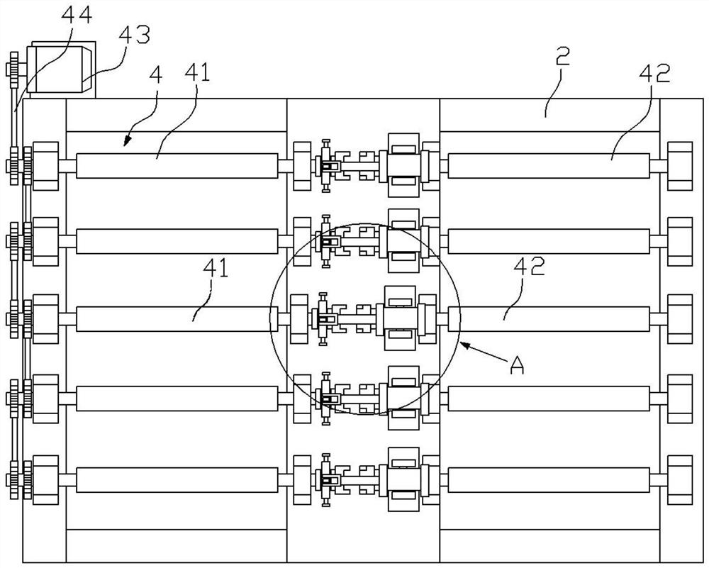
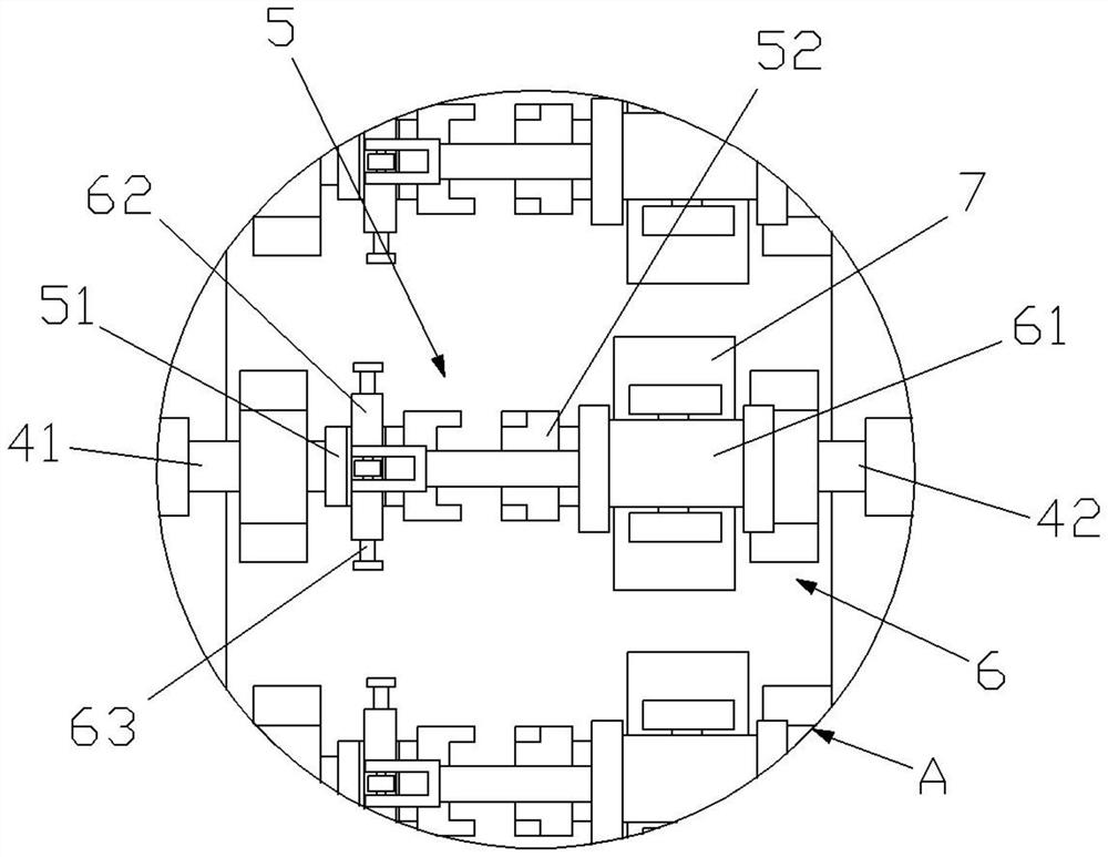
[0019] see figure 1 , figure 2 , image 3 , a conveyor belt device for steel strip processing, including a base 1, a top plate 2, a lifting mechanism 3, a transmission mechanism 4, an engaging structure 5, several driving mechanisms 6 and several support frames 7.

[0020] The base 1 is set on the ground, and the top plate 2 is liftably set above the base 1 for installing the transmission mechanism 4 .

[0021] The lifting mechanism 3 is located between the base 1 and the top plate 2. In this embodiment, there are two lifting mechanisms 3, which are respectively arranged on both sides of the base 1, and are used to drive the top plate ...


PUM


Abstract

The invention discloses a conveyor belt device for steel belt machining. The conveyor belt device comprises a base, a top plate, a lifting mechanism, a conveying mechanism, a clamping structure and a plurality of driving mechanisms, wherein the top plate is arranged above the base in a liftable mode, the lifting mechanism is arranged between the base and the top plate, and the conveying mechanism comprises a plurality of first conveying rollers and a plurality of second conveying rollers; the first conveying rollers are arranged on one side of the top face of the top plate,and the second conveying rollers are arranged on the other side of the top face of the top plate; the clamping structure comprises a sliding clamping sleeve and a fixed clamping sleeve, wherein the sliding clamping sleeve slidably sleeves one end of each first conveying roller, and the fixed clamping sleeve fixedly sleeves one end of each second conveying roller; and the driving mechanisms are arranged on the top plate, and are used for driving the corresponding sliding clamping sleeves to relatively slide towards the fixed clamping sleeves in the axis directions of the sliding clamping sleeves, so that the sliding clamping sleeves and the fixed clamping sleeves are clamped or separated, and the first conveying rollers and the second conveying rollers are connected or separated. Single-channel plate conveying or multi-channel plate conveying can be achieved.

Description

technical field [0001] The invention relates to the field of stainless steel strip processing, in particular to a conveyor belt device for steel strip processing. Background technique [0002] In the steel strip processing, after the steel strip is processed and cut into sheets of steel plates, the steel plates need to be transported to the preset station by the steel plate transfer device for transfer or processing. The sheared steel plates have various specifications and need to be transported separately by the steel plate transfer device or by using multiple steel plate transfer devices of different specifications to transport the steel plates. When it is necessary to transport multiple steel plates at the same time or at intervals to different stations, the existing conveyor belt device is not suitable for transporting steel plates of various specifications. Contents of the invention [0003] In order to solve the above problems, the present invention provides a conve...

Claims


Application Information

Patent Timeline
Patent Type & Authority Applications(China)
IPC IPC(8): B65G13/07B65G13/12B65G39/12
CPCB65G13/07B65G13/12B65G39/12Y02P70/10
Inventor 陈元刘慧丹熊淼华刘石雄罗亮
Owner ZHAOQING HONGWANG METAL IND
Why Eureka
Try Eureka