
Compressible turbulent fluid topological optimization method based on automatic differentiation

A topology optimization and automatic differentiation technology, applied in the direction of constraint-based CAD, design optimization/simulation, complex mathematical operations, etc., can solve the problems of insufficient flexibility, error-prone, cumbersome process of compressible fluid adjoint equations, etc. Maintenance and flexibility, the effect of reducing the burden

Pending Publication Date: 2022-02-08
XIAMEN UNIV
View PDF0 Cites 0 Cited by
  • Summary
  • Abstract
  • Description
  • Claims
  • Application Information

AI Technical Summary

Problems solved by technology

[0005] The purpose of the present invention is to provide fluid topology optimization for compressible fluids, and consider the influence of the turbulence model on the optimization, construct the adjoint equation through the automatic differentiation method, and use the characteristics of the automatic differentiation method to generate the Jacobian matrix efficiently and accurately. A topology optimization method for compressible turbulent fluids based on automatic differentiation to avoid problems such as manual derivation of adjoint equations for compressible fluids with insufficient flexibility, tedious process and error-prone

Method used


Image

  • Compressible turbulent fluid topological optimization method based on automatic differentiation
  • Compressible turbulent fluid topological optimization method based on automatic differentiation
  • Compressible turbulent fluid topological optimization method based on automatic differentiation

Examples


Embodiment Construction

[0058] The specific implementation manners of the embodiments of the present invention will be described in detail below in conjunction with the accompanying drawings. For the purpose of explanation rather than limitation, specific details are set forth in the following description to help a comprehensive understanding of the present invention.

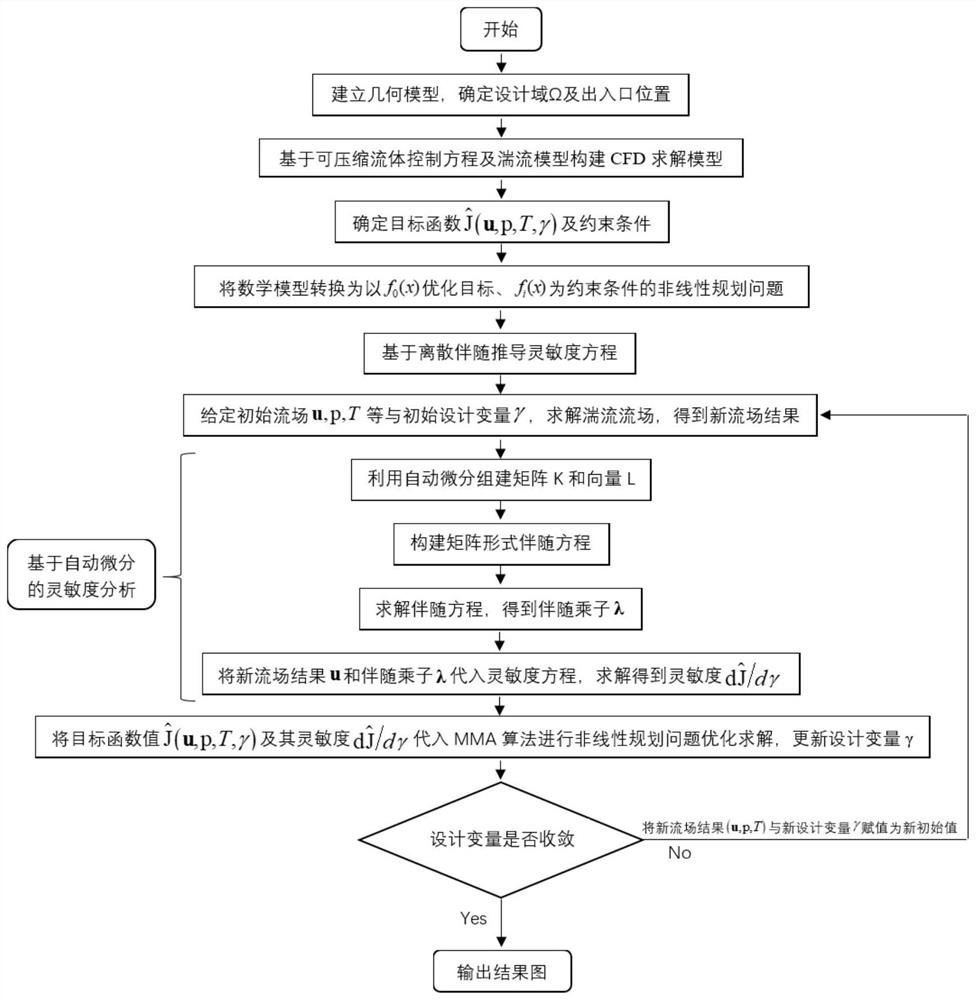
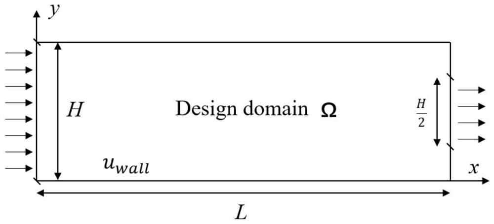
[0059] Taking the optimization of compressible turbulent flow in a simple two-dimensional straight channel as an example, the main construction process of the compressible fluid topology optimization method based on automatic differential solution with sensitivity is detailed in figure 1 . The main method of this embodiment is as follows:

[0060] 1. According to the requirements of the straight channel embodiment, construct a square design domain Ω, such as figure 2 . The left side is the entrance, and the right side is the exit, so that the width of the entrance is twice the width of the exit;

[0061] 2. Set the basic parameter...


PUM


Abstract

The invention discloses a compressible turbulent fluid topological optimization method based on automatic differentiation, and relates to topological optimization. The method comprises the steps: establishing a geometric model corresponding to flow channel topological optimization; acquiring the basic parameters of a topological optimization object, and constructing a CFD topological optimization model; constructing a target function according to the basic parameters, and forming a nonlinear programming problem; deriving a sensitivity equation based on an adjoint method; solving the fluid control equation to obtain a flow field result and a value of a target function, and outputting a new flow field result; building a Jacobian matrix and a gradient vector by using an automatic differential technology; establishing a matrix form adjoint equation to obtain an adjoint multiplier; substituting the new flow field result and the adjoint multiplier into a sensitivity equation to solve the sensitivity; establishing a mathematical model by using an MMA numerical optimization method in combination with a nonlinear programming problem; carrying out optimization solution on the flow channel, updating design variables to obtain an optimal solution, and outputting an optimal two-dimensional topological configuration. And the problems of insufficient flexibility, tedious process, error proneness and the like of manual derivation of a compressible fluid accompanying equation are avoided.

Description

technical field [0001] The invention belongs to the technical field of fluid topology optimization in computational fluid dynamics, in particular to an automatic differential-based compressible turbulent fluid topology optimization method. Background technique [0002] Compressibility is one of the inherent properties of all fluids, which is usually ignored in water and other liquids, but for gases such as air, compressibility is a critical consideration at high speed and high pressure one. High-speed compressible fluid flow widely exists in the aerospace field, and the compressibility of fluid must be considered in aerodynamic design such as engine flow path components, aircraft shape, airfoil profile, and turbomachinery. At the same time, with the development of computer technology, optimization methods for compressible flows have emerged one after another, Cummings et al. ([1]Cummings R M, Yang H T, Oh YH. Supersonic, turbulent flow computation and drag optimization for ...

Claims


Application Information

Patent Timeline
Patent Type & Authority Applications(China)
IPC IPC(8): G06F30/28G06F17/13G06F111/04G06F111/10G06F113/08G06F119/14
CPCG06F30/28G06F17/13G06F2111/10G06F2111/04G06F2113/08G06F2119/14
Inventor 邱若凡周涛尤延铖周康闫成
Owner XIAMEN UNIV
Learn More