
Chain-driven sliding door

A chain-driven, sliding-lifting technology, applied in the field of sliding doors, can solve problems such as door leaf rising obstruction, door leaf descending speed limit, wire rope breaking, etc., to prevent winding or de-grooving, force balance parallel synchronization, and prolong service life Effect

Active Publication Date: 2022-02-08
湖南省优泰门业有限公司
View PDF8 Cites 0 Cited by
  • Summary
  • Abstract
  • Description
  • Claims
  • Application Information

AI Technical Summary

Problems solved by technology

[0003] (1) The door leaf of the existing sliding door is all through the synchronous transmission of the balance mechanism and the drive motor to realize the lifting of the door leaf, which will easily cause useless work done by the balance mechanism and the drive motor, and then affect the overall use times of the slide door, thereby Reduced service life
[0004] (2) During the falling process, the door leaf of the sliding door performs free fall movement, which is driven by the gravity of the door leaf itself to achieve the decline. When the door leaf is automatically lowered by its own gravity, the uneven running speed of the door leaf causes the door leaf to run unstable, and the door leaf With the emergence of the problem of uncontrollable speed, the descending speed of the door leaf is limited, so that it is impossible to further improve the fast and efficient closing of the door leaf
[0005] (3) When the door leaf is lowered, because the wire rope and the door leaf are in a soft connection state, when the door leaf is blocked from moving downward, the motor cannot sense that the door leaf is in a blocked state, and continues to release the wire rope, making it easy for the wire rope to come out of the groove of the rope wheel and cause the door leaf Can't lift normally
[0006] (4) During the rising process of the door leaf, if an obstacle is encountered, the door leaf will be blocked from rising, while the drive motor and the balance mechanism will always be in a state of doing work, and due to the obstruction of the obstacle, it is easy to make the steel wire rope under high load force. The tension state, which may cause the wire rope to be broken
[0007] (5) When the door leaf rises until the gravity of the door leaf is completely borne by the horizontal section and the arc section of the curved rail, the gravity of the door leaf free fall is 0, and the driving force cannot be established when the door leaf falls again and cannot operate normally.

Method used


Image

  • Chain-driven sliding door
  • Chain-driven sliding door
  • Chain-driven sliding door

Examples


Embodiment Construction

[0028] The present invention will be further described below in conjunction with the accompanying drawings and embodiments.

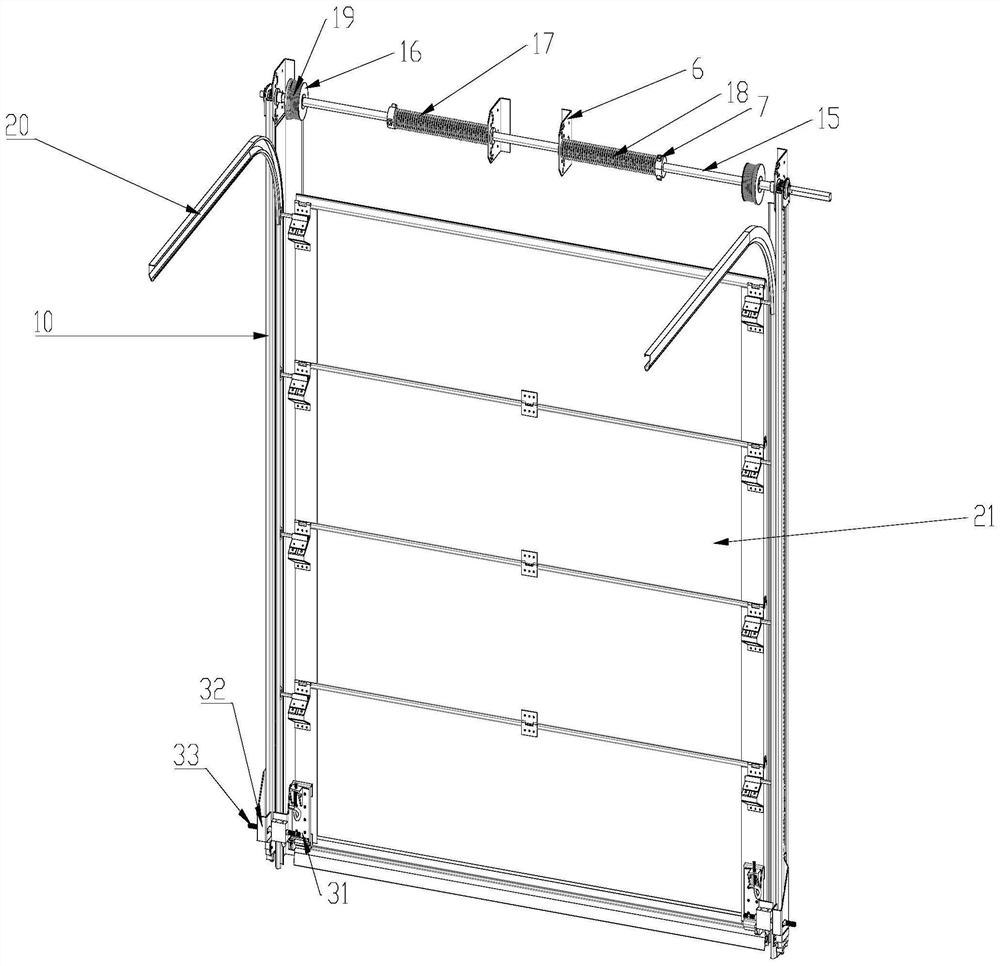
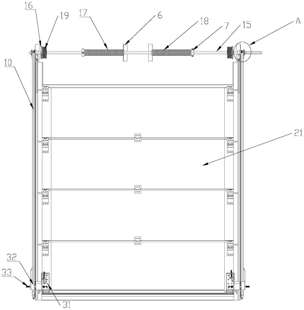
[0029] refer to Figure 1-3 As shown, this embodiment includes a straight rail frame 10 and a curved rail frame 20, the curved rail frame 20 is located in the straight rail frame 10 and is fixedly connected with the straight rail frame 10, and the curved rail frame 20 is provided with There is a door leaf 21, the inside of the curved rail frame 20 is provided with slide rails, and the two sides of the door leaf 21 are provided with pulleys, so that the door leaf 21 can lift and slide on the slide rails inside the curved rail frame 20 through the setting of the pulleys, thereby improving the height of the door leaf. 21 do the stability of slide-up motion on curved rail frame 20.

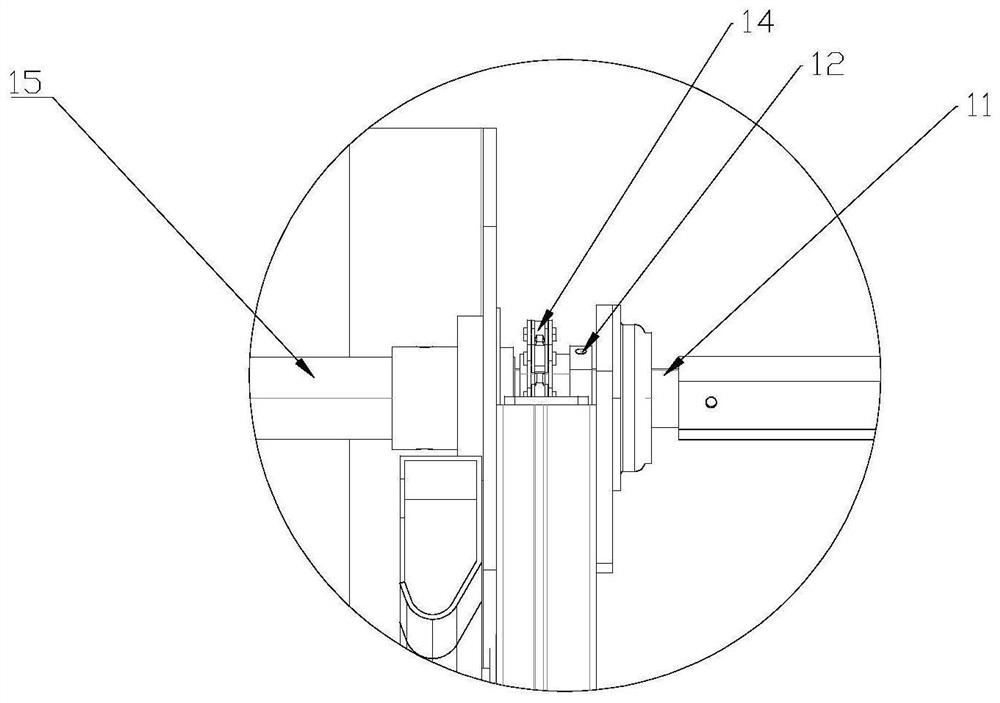
[0030] The top of the straight rail frame 10 is provided with a solid drive shaft 11, the solid drive shaft 11 is covered with a hollow drive shaft 15, the hollow drive shaft ...


PUM


Abstract

The invention discloses a chain-driven sliding door. The sliding door comprises a straight rail rack and a bent rail rack, wherein a door leaf is arranged on the bent rail rack, a solid transmission shaft is arranged on the top of the straight rail rack, a hollow transmission shaft is arranged on the solid transmission shaft in a sleeving mode, the hollow transmission shaft and the solid transmission shaft form a combined transmission shaft, and two ends of the solid transmission shaft penetrate through the straight rail rack and are fixedly connected with a chain gear I; a chain gear II corresponding to the chain gear I is arranged at the bottom of the straight rail rack, and the chain gear I and the chain gear II are connected through a chain; the two sides of the bottom of the door leaf are fixedly connected with one side of a chain at the bottom of the straight rail rack through rotating pair assemblies. The sliding door is advantaged in that the hollow transmission shaft and the solid transmission shaft are adopted to form the combined transmission shaft, so the occurrence of a stuck fault when lifting of the door leaf is blocked is greatly reduced, a phenomenon that the door leaf at the uppermost position loses the gravity effect and cannot descend is avoided, a phenomenon that a steel wire rope is wound or disengaged from a groove is completely eradicated, and the overall use quality of the sliding door is improved; meanwhile, the service life is prolonged.

Description

technical field [0001] The invention relates to a sliding door, in particular to a chain-driven sliding door. Background technique [0002] At present, the door leaf of the existing sliding door is driven by a shaft-driven motor during the rising process. The motor is installed on the solid shaft of the balance mechanism, and the motor drives the solid shaft to rotate forward and backward. Turn, release or tighten the wire rope, and the wire rope pulls the door leaf to move up and down; but the door leaf will have the following faults during the up and down movement process; [0003] (1) The door leaf of the existing sliding door is all through the synchronous transmission of the balance mechanism and the driving motor to realize the lifting of the door leaf, which is easy to cause useless work done by the balance mechanism and the driving motor, and then affects the overall use times of the sliding door, thereby Reduced service life. [0004] (2) During the falling proces...

Claims


Application Information

Patent Timeline
Patent Type & Authority Applications(China)
IPC IPC(8): E05F15/681E05F1/16E06B3/44
CPCE05F15/681E05F1/16E06B3/44E05Y2900/132
Inventor 罗承恩胡佳卿
Owner 湖南省优泰门业有限公司
Learn More