Double-time-scale voltage control method based on dynamic-static reactive power replacement mechanism

A voltage control method and time scale technology, applied in reactive power compensation, AC network voltage adjustment, reactive power adjustment/elimination/compensation, etc., can solve the problems of large dynamic reactive power resource occupation, voltage control failure, and control accuracy. Large and other problems, to achieve the effect of improving dynamic reactive power compensation capability, high voltage control accuracy, and ensuring safe and stable operation

Active Publication Date: 2022-02-01
NORTH CHINA ELECTRIC POWER UNIV (BAODING)
View PDF5 Cites 0 Cited by
  • Summary
  • Abstract
  • Description
  • Claims
  • Application Information

AI Technical Summary

Problems solved by technology

The intraday rolling optimization model based on MPC can effectively stabilize random and rapid voltage fluctuations, but it is more dependent on the accuracy of the prediction model, and the prediction error has a greater impact on the control accuracy
In this regard, some studies have proposed to improve the forecasting accuracy by improving the structure of the internal forecasting model and replacing the single forecasting model with a combined forecasting model. How to ensure the running speed of the control model on the premise of effectively improving the prediction accuracy has become a current research problem
[0005] The traditional dual-time-scale voltage control method based on MPC is difficult to deal with random and large voltage fluctuations in short time scales due to the limited control accuracy of long-term scales in some scenarios with a high proportion of new energy penetration, resulting in insufficient dynamic reactive power adjustment capabilities. problem, which can easily cause voltage control failure
In addition, this control method occupies a large amount of dynamic reactive power resources in steady-state scenarios, which weakens the anti-interference ability of the system and is not conducive to the long-term safe and stable operation of the system.

Method used


Image

  • Double-time-scale voltage control method based on dynamic-static reactive power replacement mechanism
  • Double-time-scale voltage control method based on dynamic-static reactive power replacement mechanism
  • Double-time-scale voltage control method based on dynamic-static reactive power replacement mechanism

Examples


Embodiment Construction

[0024] The dual-time-scale voltage control method based on the dynamic-static var replacement mechanism of the present invention will be described in detail below with reference to the embodiments and the accompanying drawings.

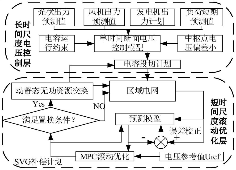
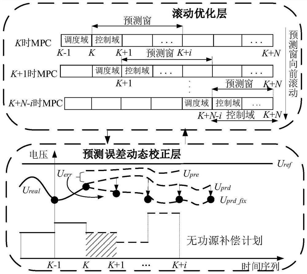
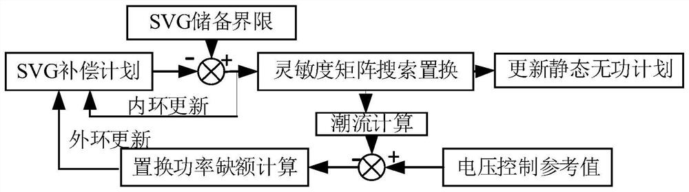
[0025] The dual-time-scale voltage control method based on the dynamic-static reactive power replacement mechanism of the present invention takes a certain regional power grid after the reactive power partition of the large power grid as a calculation example, and selects the regional dominant node as the voltage tracking control node; firstly, a dual-time scale is built For the voltage control model, the goal of the long-term scale is to minimize the voltage control deviation, considering the power flow constraints, and the short-time scale adopts rolling optimization based on improved MPC, with the goal of the minimum voltage control deviation and the consideration of the SVG climbing limit; finally, the constructed reactive power The replacement mec...


PUM


Abstract

The invention relates to a double-time-scale voltage control method based on a dynamic-static reactive power replacement mechanism; the method comprises the steps: building a long-time-scale voltage control model, using the minimum hub node voltage deviation of tracking control at all time points as a target function, and using a power grid operation power flow constraint, a capacitor bank adjusting performance constraint and a node operation voltage constraint as constraint conditions; building a short time scale rolling optimization model, taking the minimum voltage prediction control deviation at n time points in a prediction window as an objective function, and taking consideration of static var generator output lower limit and upper limit constraints, climbing constraints and power grid operation voltage constraints as constraint conditions; solving a short-time scale rolling optimization model by adopting a rolling optimization control method based on model predictive control; building a dynamic-static reactive power replacement model; and determining a capacitor compensation node switching sequence in the dynamic-static reactive power replacement process and a precedence sequence of power vacancy undertaken by the compensation nodes of the static var generator. The method can adapt to various voltage fluctuation scenes, and has high voltage control precision.

Description

technical field [0001] The invention relates to a double time scale voltage control method. In particular, it relates to a dual-time-scale voltage control method based on dynamic-static var replacement mechanism. Background technique [0002] With the depletion of traditional fossil energy and the rapid improvement of the technical level of the power industry, the transformation of energy structure has become an inevitable trend of global energy development. The clean and sustainable production of electric energy is gradually replacing traditional forms of power generation. New energy sources such as wind power and photovoltaics have achieved high-density and stable grid-connected operation in some areas, bringing considerable benefits in actual production. However, the unique randomness and volatility of new energy power generation brings great challenges to grid voltage control. How to simultaneously realize the consumption of a high proportion of new energy and ensure po...

Claims


Application Information

Patent Timeline
Patent Type & Authority Applications(China)
IPC IPC(8): H02J3/16H02J3/18
CPCH02J3/16H02J3/18H02J2300/24Y02E10/56Y02E40/10Y02E40/30
Inventor 李鹏高一航王加浩李建宜郭彦斌夏辉
Owner NORTH CHINA ELECTRIC POWER UNIV (BAODING)
Why Eureka
Try Eureka