Kaleidoscope interaction device based on multimedia technology
A kaleidoscope and multimedia technology, applied in energy-saving control technology, instruments, optics, etc., can solve the problems of poor interaction and the inability to adjust multiple styles of kaleidoscope screen changes, and achieve the effect of enhancing interest and increasing fun.
- Summary
- Abstract
- Description
- Claims
- Application Information
AI Technical Summary
Problems solved by technology
Method used
Image

Examples
Embodiment 1
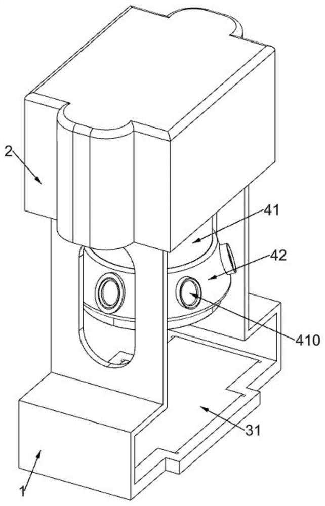
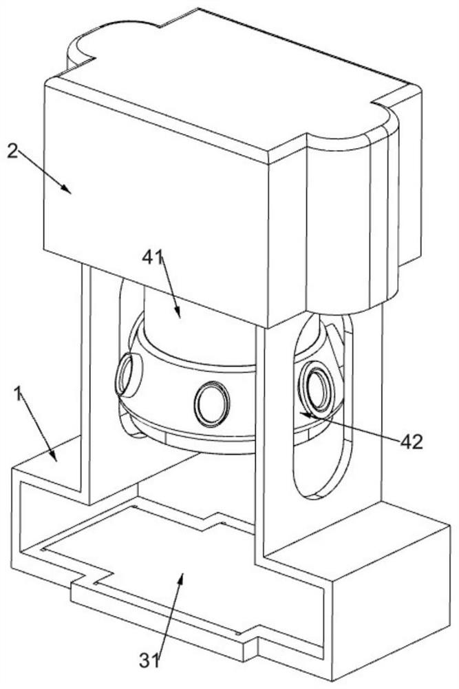
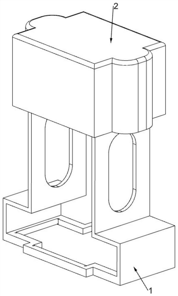
[0041] Kaleidoscope interactive installation based on multimedia technology, such as figure 1 , figure 2 , image 3 , Figure 4 , Figure 5 , Figure 6 , Figure 7 , Figure 8 , Figure 9 , Figure 10 , Figure 13 , Figure 16 and Figure 18 As shown, it includes a mounting plate frame 1, a top protective case 2, a pressure touch component 3 and a rotating component 4. The top protective shell 2 is fixedly installed on the top of the mounting plate frame 1, and the pressure touch component 3 is arranged on the mounting plate frame 1. , the pressure touch component 3 is used to adjust the mapping pattern according to the pressure, the rotation component 4 is arranged on the top surface of the mounting frame 1, and the rotation component 4 is used to control the rotation of the pattern.
[0042] The pressure touch component 3 includes a squeeze plate 31, a first return spring 32, an H-shaped slotted frame 33, an execution switch 1 34, an execution switch 2 35, a seco...
Embodiment 2
[0048] On the basis of Example 1, such as Figure 10 , Figure 11 , Figure 12 , Figure 13 As shown, it also includes an interactive adjustment component 5, the interactive adjustment component 5 is located at the bottom of the arc-shaped rotating cavity 42, the interactive adjustment component 5 is used to adjust the zoom in or out of the image, and the interactive adjustment component 5 includes a slotted limit ring 51 , hexagonal slotted frame 52 with rod, wedge-shaped baffle plate 53 and second homing spring 54, the bottom of the arc-shaped rotating cavity 42 is fixedly equipped with a slotted limit ring 51, and the slotted limit ring 51 is of sliding type Connected with a hexagonal slotted frame 52 with a rod, the hexagonal slotted frame with a rod 52 is slidably connected with a wedge-shaped baffle 53 in a hexagonal distribution manner, and the hexagonal slotted frame with a rod 52 is used to push the wedge-shaped baffle 53 to swing , two adjacent wedge-shaped baffle...
Embodiment 3
[0051] On the basis of Example 2, such as Figure 14 As shown, it also includes a light adjustment assembly 6, the slotted outer cylinder 41 is provided with a light adjustment assembly 6, the light adjustment assembly 6 is used to adjust the light irradiation angle, the light adjustment assembly 6 includes a wedge-shaped support frame 61, a light strip installation frame 62. LED lamp 63, adjusting gear one 64, rectangular slide rail frame 65, sliding rack frame 66, arc support frame 67, electric push rod 68, first return spring 69 and infrared sensor 610, slotted outer cylinder 41 There are multiple pairs of wedge-shaped support frames 61 fixedly connected inside. The two wedge-shaped support frames 61 on the same side and at the same level are connected to the light strip installation frame 62 in a co-rotating manner, and the light strip installation frame 62 is connected to LED lights 63 in a uniform arrangement. , the LED lamp 63 is used to irradiate the lights of differen...
PUM
 Abstract
Description
Claims
Application Information
 - Generate Ideas
- Intellectual Property
- Life Sciences
- Materials
- Tech Scout
- Unparalleled Data Quality
- Higher Quality Content
- 60% Fewer Hallucinations
Browse by: Latest US Patents, China's latest patents, Technical Efficacy Thesaurus, Application Domain, Technology Topic, Popular Technical Reports.
© 2025 PatSnap. All rights reserved.Legal|Privacy policy|Modern Slavery Act Transparency Statement|Sitemap|About US| Contact US: help@patsnap.com