
Integrated injector

An injector and main body technology, which is applied in the field of integrated injectors, can solve the problems that the oxidant and the fuel are not mixed evenly, the service life of the injector is affected, the injector is abnormally high temperature, etc., and the processing cycle is shortened and the weight is light. , the effect of avoiding safety hazards

Active Publication Date: 2022-02-01
合肥中科重明科技有限公司 +1
View PDF4 Cites 0 Cited by
  • Summary
  • Abstract
  • Description
  • Claims
  • Application Information

AI Technical Summary

Problems solved by technology

[0003] In the prior art, the injector is mixed with oxidant to stabilize combustion, but the mixing of oxidant and fuel in the injector is not uniform enough, and it leads to abnormally high temperature of the lower wall of the injector during combustion, which not only reduces combustion rate, and also affects the service life of the injector

Method used


Image

  • Integrated injector
  • Integrated injector

Examples


Embodiment 1

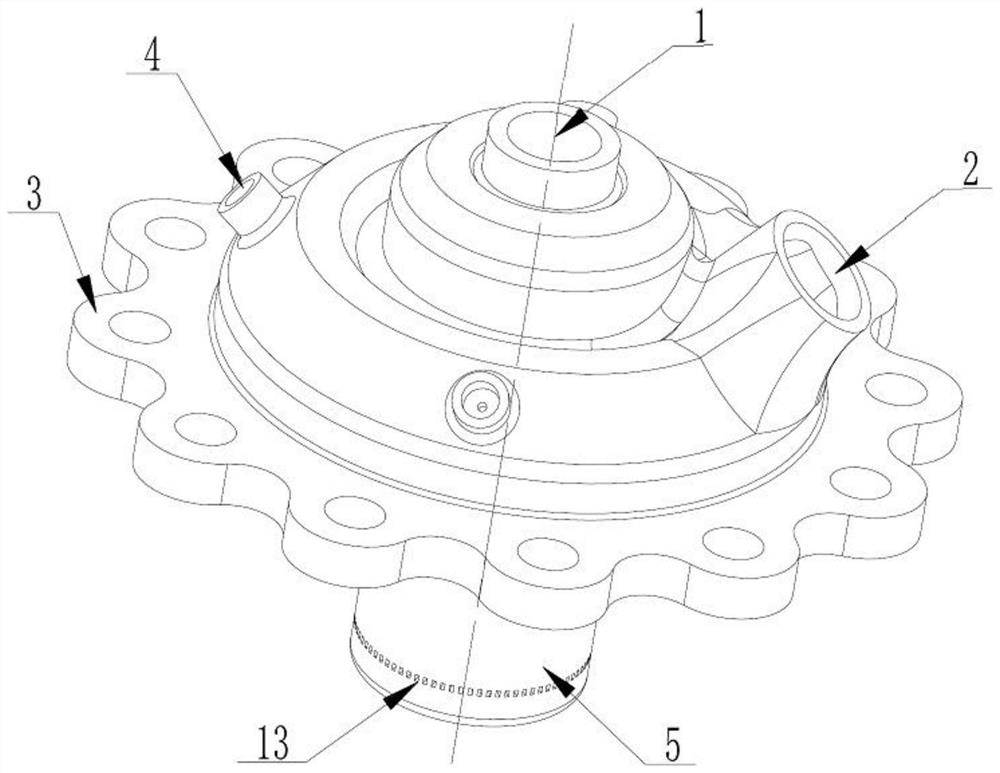
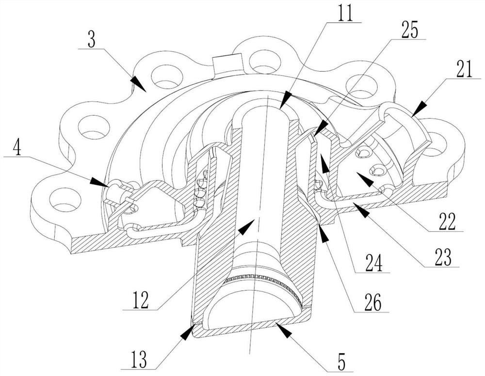
[0035] Figure 1-2 An embodiment of the present invention: an integrated injector, including an injector body 1, a mounting flange 3 located on the outer edge of the injector body 1, a test interface 4 on the outer wall of the injector body 1, and The injector head 5 located in the central area of ​​the bottom of the injector body 1 is added in the injector body 1 to improve the circumferential uniformity of the oxidant flow rate and effectively cool the lower wall surface of the injector body 1. The oxidant flow channel part 2, In the present invention, since the oxidant flow channel part is added in the main body of the injector, the circumferential uniformity of the oxidant flow rate can be ensured through the complex oxidant channel arrangement, and at the same time, the oxidant is used to effectively cool the lower wall of the injector, which can improve the injection efficiency. life of the injector.

[0036] The oxidant flow channel part 2 includes an oxidant inlet 21 ...

Embodiment 2

[0053] The cooling channel 23 includes a total of 30 sub-channels, and the cross-sectional shape of each sub-channel is raindrop-shaped, which is beneficial to 3D printing.

Embodiment 3

[0055] The width of the buffer slit 25 should be small enough, in this embodiment, the width is 4 mm, and its pressure holding effect makes the oxidant in the buffer chamber 24 evenly distributed in the circumferential direction.


PUM


Abstract

The invention relates to the technical field of engine injectors, in particular to an integrated injector. The injector comprises an injector main body, a mounting flange located on the edge of the outer side of the injector main body, a test interface located on the outer wall of the injector main body and an inspiration head located in the center area of the bottom of the injector main body. An oxidizing agent runner part which is used for improving the circumferential uniformity of the flow of an oxidizing agent and effectively cooling the lower wall surface of the injector main body is additionally arranged in the injector main body, and comprises an oxidizing agent inlet and an oxidizing agent outlet which form an oxidizing agent channel in the injector main body, and a collection cavity, a cooling channel, a buffer cavity and a buffer slit are sequentially arranged between the oxidant inlet and the oxidant outlet. The purpose of guaranteeing the circumferential uniformity of the flow of an oxidizing agent is achieved, meanwhile, the lower wall face of the injector is effectively cooled through the oxidizing agent, and the service life of the injector can be prolonged.

Description

technical field [0001] The invention relates to the technical field of engine injectors, in particular to an integrated injector. Background technique [0002] The injector of a rocket engine is an important component for injecting fuel and oxidant into the combustion chamber in a certain proportion for full atomization and mixing. The fuel and oxidant form a complex cavity flow path inside the injector, so as to ensure that the loss of flow resistance is small , but also to ensure high structural strength, but also to ensure that high temperature does not fail. Therefore, the injector is constantly developing towards the direction of simplifying the structure, reducing the weight and improving the reliability. [0003] In the prior art, the injector is mixed with oxidant to stabilize combustion, but the mixing of oxidant and fuel in the injector is not uniform enough, and it leads to abnormally high temperature of the lower wall of the injector during combustion, which not...

Claims


Application Information

Patent Timeline
Patent Type & Authority Applications(China)
IPC IPC(8): F02K9/52
CPCF02K9/52
Inventor 赵林英鲁碧为袁越明范学军
Owner 合肥中科重明科技有限公司
Learn More