Blade protection device for multi-rotor unmanned aerial vehicle and multi-rotor unmanned aerial vehicle
A technology of a multi-rotor unmanned aerial vehicle and a protective device, which is applied in the field of unmanned aerial vehicles, can solve the problems of inconvenient and quick loading and unloading, and the structure of the blade protective cover is complicated, and achieves the effect of avoiding the bombing of the aircraft.
- Summary
- Abstract
- Description
- Claims
- Application Information
AI Technical Summary
Problems solved by technology
Method used
Image
Examples
Embodiment 1
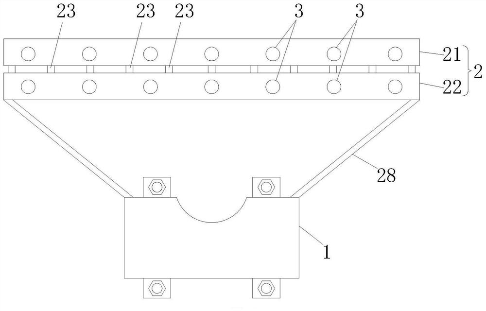
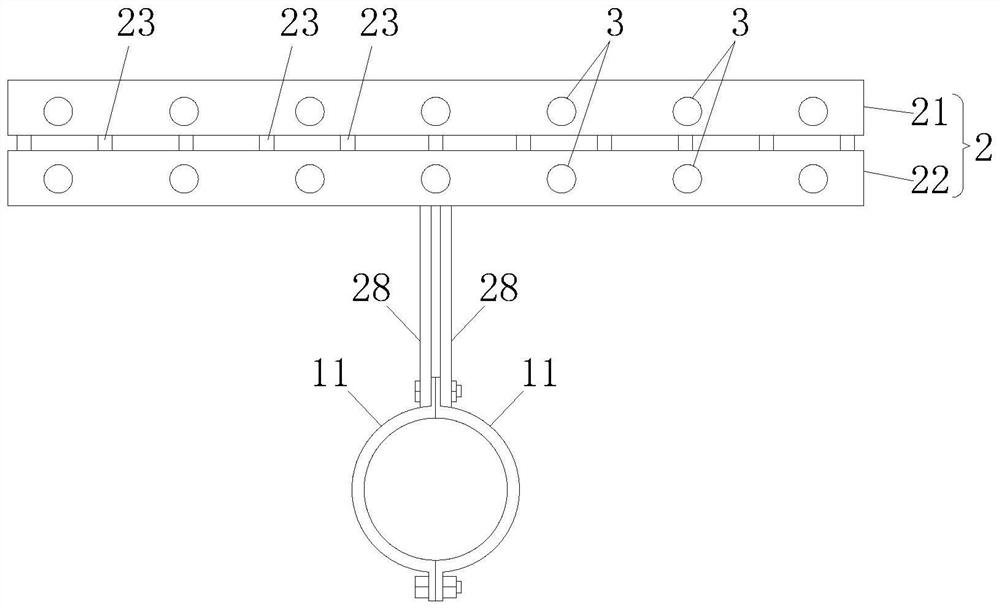
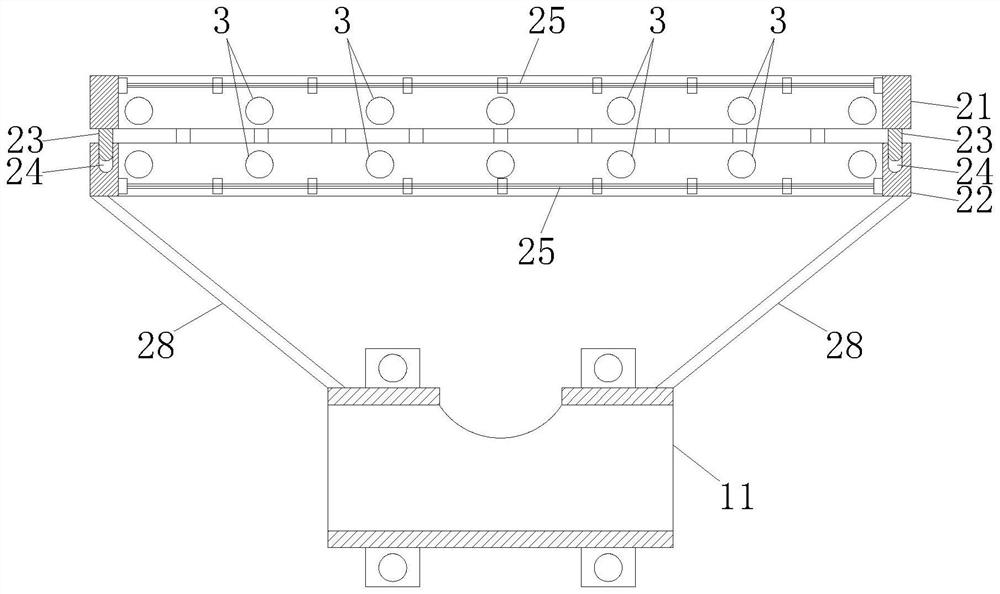
[0028] A blade protection device for multi-rotor drones, such as Figure 1-4 As shown, it includes bracket 1 and net cover 2. Among them, the bracket 1 is used to detachably connect with the arm of the multi-rotor UAV when the device is in use, and the net cover 2 is used to enclose the blades of the multi-rotor UAV when the device is in use. Carry out isolation protection.
[0029] In this embodiment, the bracket 1 includes two clamping members 11 each having a receiving groove, and the two clamping members 11 are detachably connected to each other by bolts or screws. And when the two clamping members 11 are connected to each other by bolts or screws, the two accommodating grooves are butted with each other, and the accommodating holes formed after the abutment are adapted to the arms of the multi-rotor UAV. For example, when the cross-section of the side wall of the arm of the multi-rotor UAV is circular, the above-mentioned accommodating groove is correspondingly configur...
Embodiment 2
[0039] A multi-rotor UAV, such as Figure 5 As shown, it includes a fuselage 4, a plurality of arms 5 connected to the fuselage 4, and a lift assembly installed on each arm 5. The lift assembly includes a motor and a paddle mounted on the output shaft of the motor, each Each blade is equipped with the blade protection device disclosed in Embodiment 1. And it can be understood that the output shaft of the motor passes through the protective net 25 connected to the lower shroud ring 21 and then connects with the paddle located in the accommodating gap. In addition, a notch is provided on the clamping member 11, so that after the two clamping members 11 are docked, the motor can pass through the through hole surrounded by the two notches.
PUM
 Abstract
Description
Claims
Application Information
 - R&D
- Intellectual Property
- Life Sciences
- Materials
- Tech Scout
- Unparalleled Data Quality
- Higher Quality Content
- 60% Fewer Hallucinations
Browse by: Latest US Patents, China's latest patents, Technical Efficacy Thesaurus, Application Domain, Technology Topic, Popular Technical Reports.
© 2025 PatSnap. All rights reserved.Legal|Privacy policy|Modern Slavery Act Transparency Statement|Sitemap|About US| Contact US: help@patsnap.com


