Active ankle joint rehabilitation training device
A kind of rehabilitation training, active technology, applied in the direction of muscle training equipment, sports accessories, gymnastics equipment, etc., can solve the problem of unable to load force adjustment, and achieve the effect of slowing down the reset speed, avoiding secondary injury, and avoiding improper rehabilitation.
- Summary
- Abstract
- Description
- Claims
- Application Information
AI Technical Summary
Problems solved by technology
Method used
Image

Examples
Embodiment 1
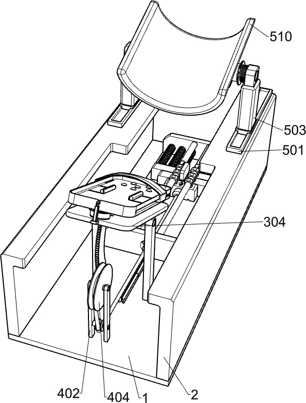
[0033] An active ankle joint rehabilitation training device, such as Figure 1-13 As shown, it includes a base plate 1, a support plate 2, a pedal mechanism and a load mechanism. There are two support plates 2, and the two support plates 2 are respectively fixed on the left and right parts of the upper surface of the base plate 1. The pedal mechanism is arranged on Above the front part of the base plate 1, the load mechanism is arranged on the rear part of the upper surface of the base plate 1, and the pedal mechanism and the load mechanism cooperate mechanically.
[0034] When using the device, the medical staff will help the patient to sit on the chair. First, the medical staff will place the device on the ground in front of the patient. The patient will place the injured foot on the pedal mechanism. At the same time, the medical staff will adjust the pedal mechanism to The patient's foot is fixed. According to the different periods of the patient's recovery, the medical sta...
Embodiment 2
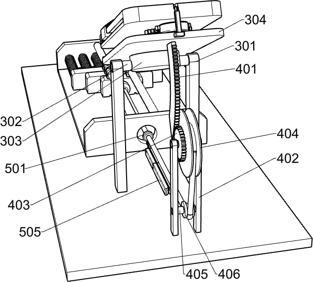
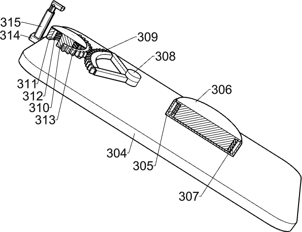
[0036] On the basis of Example 1, such as Figure 3-Figure 5 As shown, the pedal mechanism includes a first support frame 301, a first rotating shaft 302, a first fixed block 303, a fixed plate 304, a torsion assembly, a pedal 319, an L-shaped slider 320, a second tension spring 321, an elastic Bar 322, slide bar 323 and first spring 324, the first support frame 301 is fixed on the front part of the upper surface of the bottom plate 1, the first rotating shaft 302 is connected to the upper part of the first support frame 301 in rotation, and the first fixing block 303 is fixed on In the middle of the first rotating shaft 302, the upper surface of the first fixed block 303 is affixed with a fixed plate 304, the upper surface of the fixed plate 304 is provided with a torsion assembly, the upper surface of the fixed plate 304 is provided with a pedal 319, and the left and right walls of the pedal 319 A chute is provided respectively, and two L-shaped sliders 320 are arranged in t...
Embodiment 3
[0043] On the basis of Example 2, such as Figure 9-Figure 11 As shown, a leg support mechanism is also included, and the leg support mechanism includes a guide plate 501, an electric slider 502, an electric push rod 503, a second spline shaft 504, a sliding sleeve 505, a second spring 506, a support block 507, a first The five rotating shafts 508, the third torsion spring 509 and the U-shaped leg rest 510 are provided with two guide plates 501 in total. There is a chute, and the chute provided on the upper part of the two guide plates 501 is respectively slidingly connected with an electric slider 502, and the upper surface of the electric slider 502 is fixed with an electric push rod 503, and the upper end of the telescopic rod of the electric push rod 503 on the right is The fifth rotating shaft 508 is fixedly connected, and the left part of the second spline shaft 504 is slidably connected with a sliding sleeve 505. The left side of the sliding sleeve 505 is provided with ...
PUM
 Abstract
Description
Claims
Application Information
 - R&D
- Intellectual Property
- Life Sciences
- Materials
- Tech Scout
- Unparalleled Data Quality
- Higher Quality Content
- 60% Fewer Hallucinations
Browse by: Latest US Patents, China's latest patents, Technical Efficacy Thesaurus, Application Domain, Technology Topic, Popular Technical Reports.
© 2025 PatSnap. All rights reserved.Legal|Privacy policy|Modern Slavery Act Transparency Statement|Sitemap|About US| Contact US: help@patsnap.com