
Lens assembly driving apparatus and camera module comprising same

A technology of lens assembly and driving equipment, applied in the direction of camera, electric assembly, focusing device of camera, etc., can solve problems such as angle of view change, magnetic field interference, defocus, etc., to minimize eccentricity or tilt phenomenon, prevent magnetic field interference, eliminate The effect of size restrictions

Pending Publication Date: 2022-01-28
LG INNOTEK CO LTD
View PDF5 Cites 0 Cited by
  • Summary
  • Abstract
  • Description
  • Claims
  • Application Information

AI Technical Summary

Problems solved by technology

[0018] According to recent technological trends, ultra-thin and ultra-compact camera modules are required, but the space for OIS operation in ultra-compact camera modules is limited, so there is a problem that it is difficult to implement the OIS function applied to general large cameras, and when applying OIS drivers , there is a problem that ultra-thin and ultra-compact camera modules cannot be realized
[0019] In addition, in the conventional OIS technology, within the limited size of the camera module, since the OIS drive unit is arranged on one side of the physical lens assembly, there is a problem that the lens size for OIS is limited, making it difficult to ensure the amount of light
[0020] In particular, in order to obtain the best optical characteristics from the camera module, when OIS is implemented by lens movement or module tilt, the alignment between the lens groups must be good, but in the prior art OIS technology, when off-center (i.e., the lens When the center of the sphere between the groups deviates from the optical axis), or tilting (i.e., the phenomenon of tilting the lens), there will be a problem that the viewing angle is changed or out of focus, which will adversely affect the image quality or resolving power
[0021] In addition, in the conventional OIS technology, AF or zooming can be implemented while OIS is driven, but due to the space limitation of the camera module and the location of the driving part of the existing OIS technology, the magnet for OIS and the AF or zooming The magnets are positioned close to each other, causing magnetic field interference, preventing OIS from operating properly, and causing eccentricity or tilting
[0022] In addition, since a mechanical driving device is required for lens movement or module tilting, the prior art OIS technology has problems of complex structure and increased power consumption

Method used

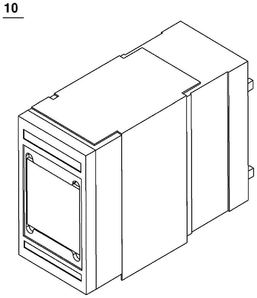
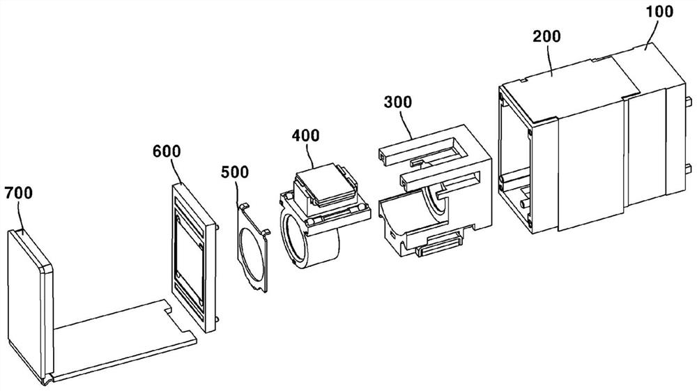
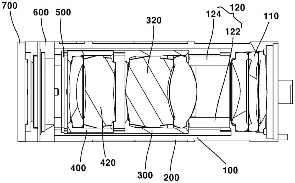

Image

  • Lens assembly driving apparatus and camera module comprising same
  • Lens assembly driving apparatus and camera module comprising same
  • Lens assembly driving apparatus and camera module comprising same

Examples


Embodiment Construction

[0085] Hereinafter, preferred embodiments of the present invention will be described in detail with reference to the accompanying drawings.

[0086] However, the technical idea of ​​the present invention is not limited to some embodiments to be described, but can be implemented in various forms, and within the scope of the technical idea of ​​the present invention, one or more can be selectively combined or replaced among the embodiments. Multiple constituent elements.

[0087] In addition, unless clearly defined and described, the terms (including technical terms and scientific terms) used in the embodiments of the present invention can be interpreted as meanings that can be generally understood by those skilled in the art, and can be interpreted in consideration of the contextual meaning of related technologies Explain common terms such as terms defined in dictionaries.

[0088] In addition, terms used in this specification are used to describe the embodiments and are not i...


PUM


Abstract

The present embodiment relates to a lens assembly driving apparatus comprising: a first driving unit disposed in a housing; a lens assembly disposed in the housing; and a second driving unit disposed in the lens assembly and facing the first driving unit, wherein on the basis of an optical axis direction, a first length of the first driving unit is longer than or equal to a first length of the second driving unit, and on the basis of a direction perpendicular to the optical axis direction, a second length of the first driving unit is shorter than a second length of the second driving unit.

Description

technical field [0001] The present invention relates to a lens assembly driving device and a camera module including the lens assembly driving device. Background technique [0002] The camera module photographs a subject and stores it as an image or video, and the camera module is installed in a mobile terminal such as a mobile phone, a notebook computer, a drone, and a vehicle. [0003] Meanwhile, portable devices such as smartphones, tablets, and notebooks have built-in ultra-compact camera modules, and such camera modules can perform an autofocus (AF) function that automatically adjusts the distance between the image sensor and the lens to Align the focal length of the lens. [0004] In addition, recent camera modules are capable of performing a zoom function that zooms in or out by increasing or decreasing the magnification of a distant subject through a zoom lens. [0005] In addition, recent camera modules employ image stabilization (IS) technology to correct or prev...

Claims


Application Information

Patent Timeline
Patent Type & Authority Applications(China)
IPC IPC(8): G02B7/09G02B27/64G03B13/36G03B5/00
CPCG02B7/09G02B27/646G03B13/36G03B5/00G03B5/02G02B7/021G02B7/102G03B3/10G03B2205/0015G03B2205/0069G03B2205/0046H02K41/031H04N23/00H04N23/60G02B7/08
Inventor 郑承炫具本锡
Owner LG INNOTEK CO LTD
Learn More