
Control method of optical storage and charging energy system constructed based on retired batteries

A technology of an energy system and a control method, applied in the field of optical storage and charging, can solve the problems of no retired battery optical storage and charging system, the inability to use the service life of the retired battery, the inability to ensure the state of charge of the retired battery and the balance control of charge and discharge, etc.

Pending Publication Date: 2022-01-28
BEIJING NEGO AUTOMATION TECH
View PDF0 Cites 0 Cited by
  • Summary
  • Abstract
  • Description
  • Claims
  • Application Information

AI Technical Summary

Problems solved by technology

However, in the prior art, the design of the control strategy for energy storage batteries does not take into account the performance differences between retired batteries. The charging and discharging control of retired batteries is the same as that of conventional new batteries, and it cannot ensure the different performance of retired batteries. Balanced control of battery status and charging and discharging cannot maximize the service life of various types of decommissioned batteries
Moreover, there is no solar storage charging system constructed entirely of decommissioned batteries, and this case arose from this

Method used


Image

  • Control method of optical storage and charging energy system constructed based on retired batteries
  • Control method of optical storage and charging energy system constructed based on retired batteries
  • Control method of optical storage and charging energy system constructed based on retired batteries

Examples


Embodiment Construction

[0073] The following will clearly and completely describe the technical solutions in the embodiments of the present invention with reference to the drawings in the embodiments of the present invention.

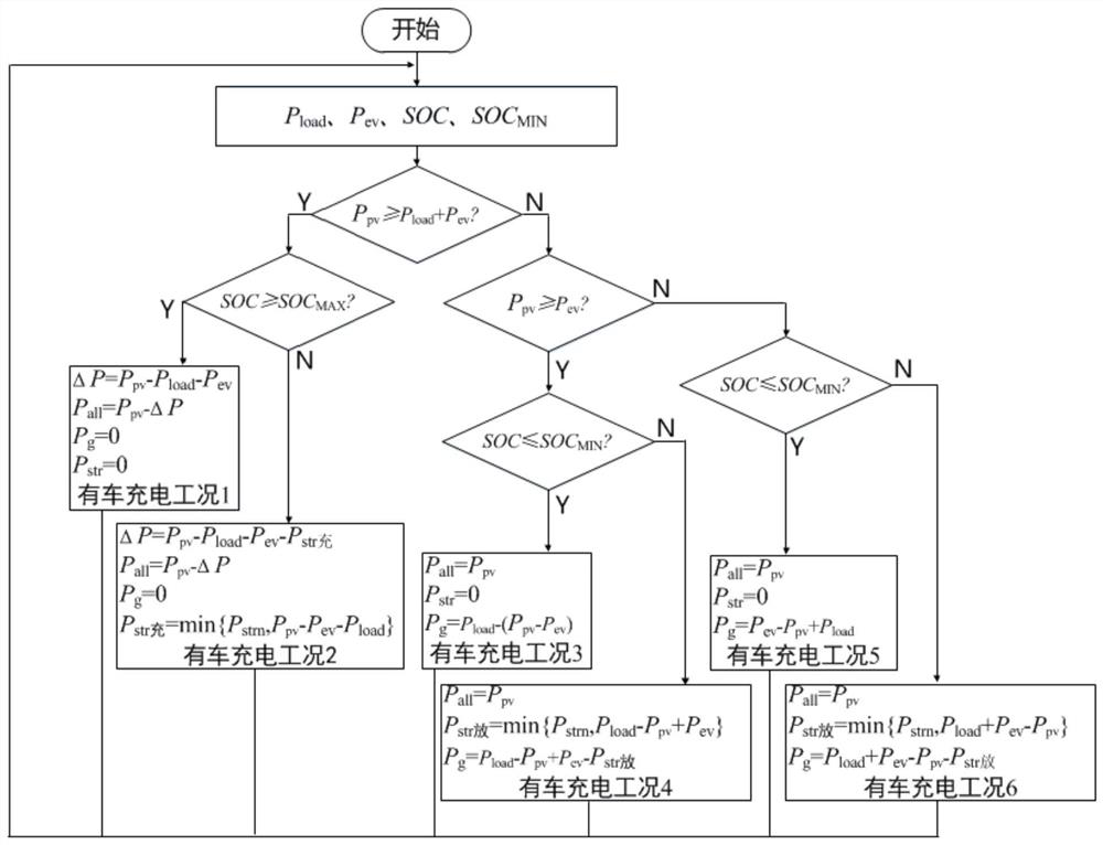
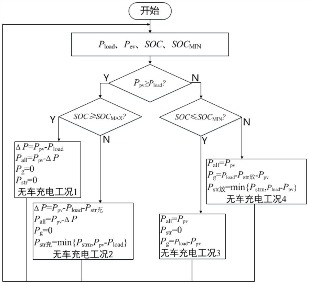
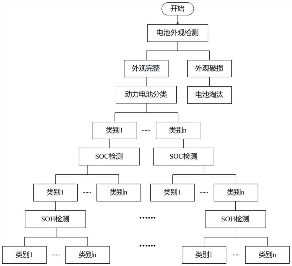
[0074] This embodiment discloses a control method for an optical storage charging source system based on decommissioned batteries. In order to better understand the entire control process, first use Figure 6 The structure shown is used to build a solar storage charging energy system based on decommissioned batteries, and the control method provided by the present invention is not limited to only applicable to Figure 6 The structure in , can be applied to any optical storage and charging system that uses decommissioned batteries as energy storage components. For simplicity, this embodiment only gives an auxiliary description of one of the structures.

[0075] Figure 6 The constructed optical storage charging station can be decomposed into four components according to the di...


PUM


Abstract

The invention relates to a control method of an optical storage and charging energy system constructed based on retired batteries. An energy storage module in the optical storage and charging energy system is divided into multiple groups of energy storage units, each group of energy storage units comprises multiple retired battery packs, and DC / DC converters connected with the retired battery packs in the same group of energy storage units are cascaded together; the energy dispatching system controls charging and discharging management of the energy storage module according to the relation between the real-time output power of the photovoltaic power generation module and the electrical load demand and the relation between the total real-time charge state of the energy storage module and a set total charge state threshold value; an intra-group charge state threshold value is set for each group of energy storage units, and during charging and discharging control, the energy storage units which reach the set intra-group charge state threshold value are controlled to stop charging and discharging; and for each group of energy storage units needing charge and discharge control, calculating real-time charge and discharge power of the group of energy storage units according to the charge and discharge weight of each group of energy storage units and the rated charge and discharge power of the group of energy storage units.

Description

technical field [0001] The invention relates to the field of optical storage and charging, in particular to a control method for an optical storage and charging energy system based on decommissioned batteries. Background technique [0002] Due to the advantages of energy saving and environmental protection, electric vehicles can effectively alleviate energy shortages, reduce air pollution and other issues, and have become an irreversible trend in the development of the automobile industry. With the rapid development of electric vehicles, the use of batteries in electric vehicles is increasing. When the capacity of electric vehicle batteries drops to 80% of the initial capacity, it is not suitable to continue to use them. If the batteries are directly eliminated, it will cause huge resources. waste. In order to maximize the use of the remaining value of the vehicle power battery and prolong the service life of the power battery, the reasonable step-by-step utilization of the...

Claims


Application Information

Patent Timeline
Patent Type & Authority Applications(China)
IPC IPC(8): H02J7/00H02J7/35H02J3/38H02J3/46H01M10/44
CPCH02J7/0016H02J7/0048H02J7/005H02J7/0068H02J7/35H02J3/381H02J3/466H01M10/441H02J2300/24Y02E10/56Y02E60/10
Inventor 陈冲赵天宇贾利民金成日梁立中
Owner BEIJING NEGO AUTOMATION TECH
Learn More