
Precise control system and method for lateral clamping parking robot

A precise control and robot technology, applied in the field of parking robots, can solve the problems that the vehicle is easy to slip and cannot be squeezed on the fork arm, and achieve the effect of avoiding falling off again and high feasibility

Pending Publication Date: 2022-01-25
JIANGSU LITTLE WHITE RABBIT INTELLIGENT MFG SCI INC
View PDF0 Cites 0 Cited by
  • Summary
  • Abstract
  • Description
  • Claims
  • Application Information

AI Technical Summary

Problems solved by technology

[0004] In view of the above-mentioned technical problems in the prior art, one of the objectives of the present invention is to solve the problem that the existing two-jaw parking robot cannot squeeze the vehicle onto the fork arm when carrying a vehicle with a large difference between the front and rear counterweights. To solve the technical problems and the problem that the vehicle is easy to slip, design a precise control system and precise control method for a side clamping parking robot with a stop arm structure

Method used


Image

  • Precise control system and method for lateral clamping parking robot
  • Precise control system and method for lateral clamping parking robot
  • Precise control system and method for lateral clamping parking robot

Examples


Embodiment 1

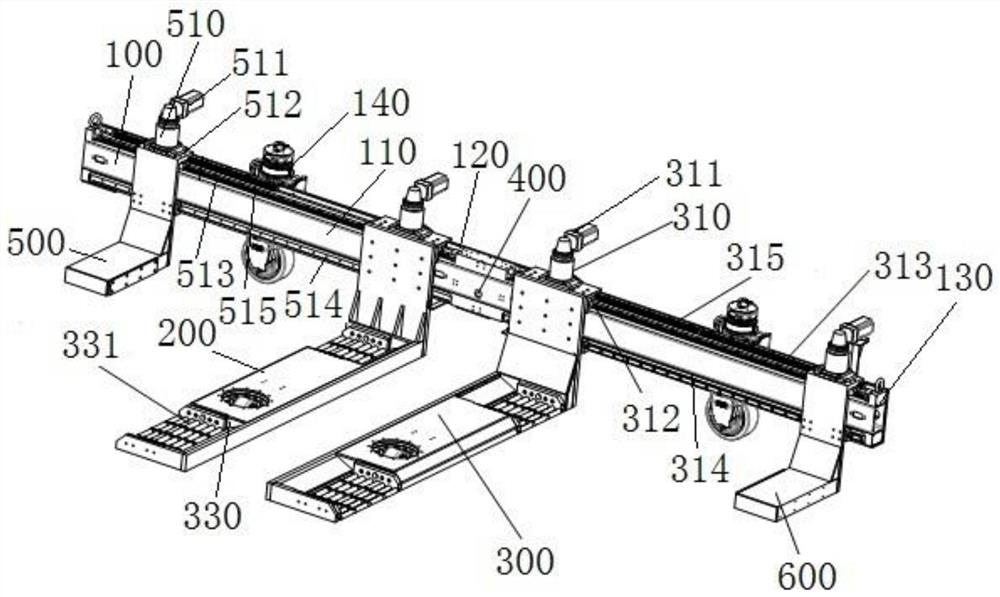
[0063] This embodiment relates to a side clamping parking robot with a stop arm structure, such as figure 1 As shown, the robot includes:

[0064] Vehicle frame 100, the vehicle frame 100 is a straight structure, and its length is fixed;

[0065] Active running device 140, the active running device 140 is installed on the vehicle frame 100, and is used to drive the vehicle frame 100 to move;

[0066] The left fork arm 200 and the right fork arm 300 with the same symmetrical structure are installed on the same side of the vehicle frame 100 respectively, and the distance between them is adjustable;

[0067] Universal wheels, the universal wheels are installed on the left fork arm 200 and the right fork arm 300 to meet the driving requirements of the parking robot and serve as a supporting structure;

[0068] The left arm 500 and the right arm 600 with the same symmetrical structure, the left arm 500 and the right arm 600 are movably installed on the vehicle frame 100, respecti...

Embodiment 2

[0083] In this embodiment, it relates to a parking robot with a stop arm, such as Figure 5 shown. The parking robot has a similar structure to the parking robot in Embodiment 1, only the structures of the left arm 500 and the right arm 600 are different.

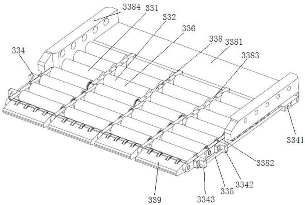
[0084] Wherein, a hub limiting seat 330 is installed on the position corresponding to the tire on the left blocking arm 500 and the right blocking arm 600 , and a tire bracket 331 is installed in the wheel hub limiting seat 330 .

Embodiment 3

[0086] This embodiment relates to a control system and a control method applicable to Embodiment 1.

[0087] Such as Figure 4 As shown, the control system of the parking robot with stop arm structure includes a traveling module, a fork arm moving module, a stop arm moving module, a measuring module, a navigation module and a general controller.

[0088] The traveling module includes an active traveling device 140 and universal wheels, which are used to drive the parking robot to move according to the traveling control instructions issued by the general controller;

[0089] The yoke moving module includes a yoke moving device 310 for driving the yoke to move;

[0090] The blocking arm moving module includes a blocking arm moving device 510 for driving the blocking arm to move;

[0091] The measurement module, including photoelectric sensors, is used to detect the wheelbase and wheel diameter of the vehicle, and calculate the stopping distance;

[0092] The navigation module...


PUM


Abstract

The invention belongs to the technical field of parking robots, and discloses a precise control system and method for a lateral clamping parking robot. The control system comprises an advancing module, a fork arm moving module, a stop arm moving module, a measuring module, a navigation module and a master controller. The advancing module is used for driving the parking robot to move according to the advancing control instruction sent by the master controller; the fork arm moving module is used for driving a fork arm to move; the stop arm moving module is used for driving a stop arm to move; the measuring module is used for detecting the wheelbase of a vehicle; the navigation module is used for calculating the advancing route of the parking robot; and the master controller comprises an input and output unit, a control instruction unit, a distance judgment unit and a resistance judgment unit. According to the precise control system and method for the lateral clamping parking robot, after the stop arms make contact with a tire firstly, the positions where the fork arms should stop are judged according to the positions of the stop arms, the states of the tire and the corresponding fork arms are directly and effectively reflected, and the situation that the tire falls off again due to excessive movement of the fork arms is avoided.

Description

technical field [0001] The invention belongs to the technical field of parking robots, and relates to an automatic equipment for moving a vehicle to or from a parking space in a parking lot, in particular to a control system and a control method for laterally clamping a parking robot. Background technique [0002] With the development of the society and the improvement of the economy, the number of cars has increased sharply. The family car has become a necessary means of transportation for every household. The problem of difficult parking in every city has also followed. The driver's own method of finding a parking space to park can no longer meet the parking needs of various cities now. In order to reduce the time for finding a parking space, parking robots with different structures have appeared on the market. [0003] Among them, a parking robot that lifts the vehicle by inserting into the bottom of the vehicle from the side and clamping the tires has a wide application...

Claims


Application Information

Patent Timeline
IPC IPC(8): E04H6/42E04H6/18E04H6/30
CPCE04H6/422E04H6/182E04H6/305
Inventor 贾宝华
Owner JIANGSU LITTLE WHITE RABBIT INTELLIGENT MFG SCI INC
Learn More