
Power distribution mounting bracket capable of improving mounting precision and mounting method

A technology for mounting brackets and installation accuracy, applied in electrical components, substation/switch layout details, etc., can solve problems such as inconvenience, component orientation and position cannot be adjusted in real time, low component installation accuracy, etc., to prevent movement. Effect

Inactive Publication Date: 2022-01-21
上海东鑫电力工程安装有限公司
View PDF0 Cites 0 Cited by
  • Summary
  • Abstract
  • Description
  • Claims
  • Application Information

AI Technical Summary

Problems solved by technology

[0003] The existing technology has the following disadvantages: the existing mounting brackets are all fixedly installed inside the distribution box, which leads to the fact that after the components are fixed on the brackets, the orientation and position of the components cannot be adjusted in real time, which is not only inconvenient to use, but also Lead to low installation accuracy of components

Method used


Image

  • Power distribution mounting bracket capable of improving mounting precision and mounting method
  • Power distribution mounting bracket capable of improving mounting precision and mounting method
  • Power distribution mounting bracket capable of improving mounting precision and mounting method

Examples


Embodiment

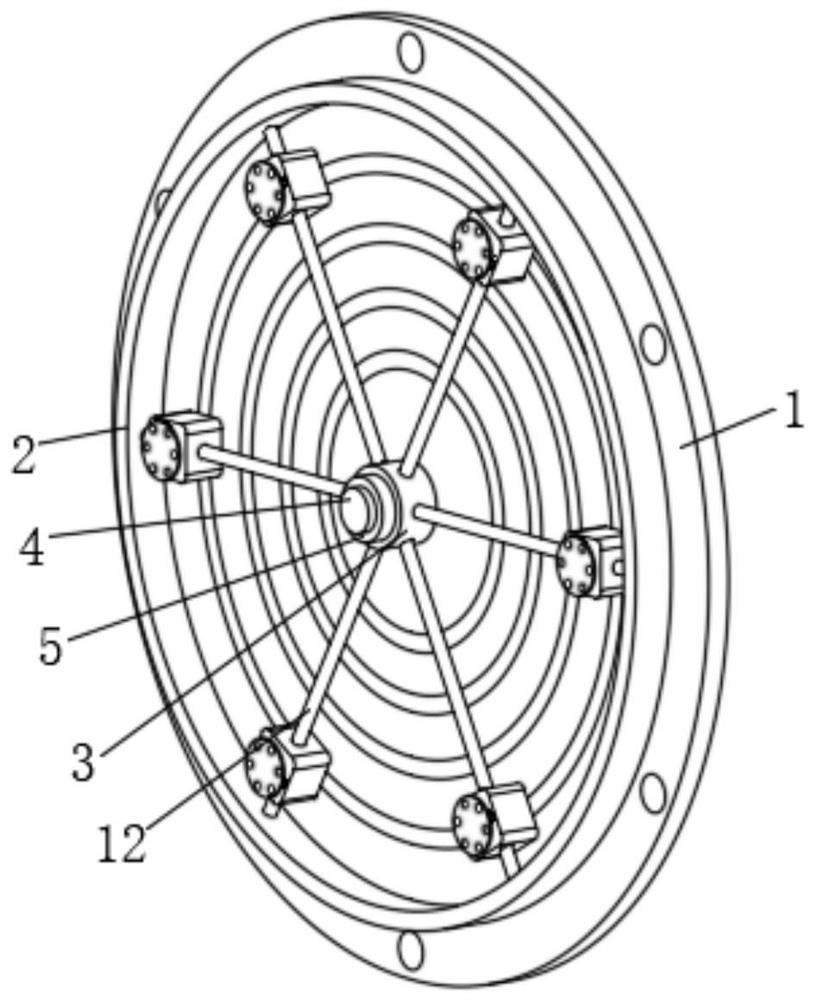
[0029] see figure 1 As shown, a power distribution installation bracket that can improve installation accuracy described in this embodiment includes a backplane 1. The difference from the prior art is that a ring frame 2 is provided on the front side of the backplane 1, and the ring frame 2 The center of the frame 2 is fixedly connected with a collar 3 through a plurality of sliding rods 12, the middle part and the front side of the backboard 1 are fixedly provided with a protruding rod 4, and the collar 3 is movably sleeved on the outer surface of the protruding rod 4;

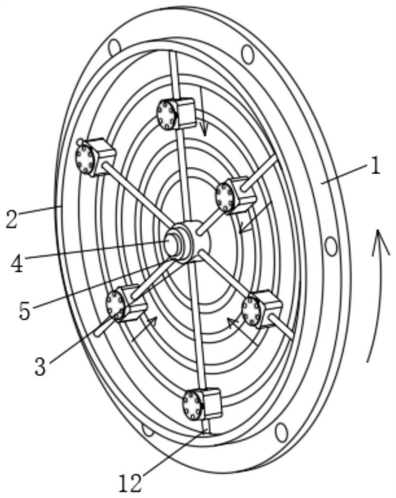
[0030] see figure 2 As shown, the inner side of the ring frame 2 is also provided with a first mounting part 6, a second mounting part 7, a third mounting part 8, a fourth mounting part 9, a fifth mounting part 10 and a sixth mounting part 11, and The first mounting part 6 , the second mounting part 7 , the third mounting part 8 , the fourth mounting part 9 , the fifth mounting part 10 and the sixth mountin...


PUM


Abstract

The invention provides a power distribution mounting bracket capable of improving the mounting precision and a mounting method. The power distribution mounting bracket comprises a back plate. Different from the prior art, an annular frame is arranged in the front side of the back plate, a lantern ring is fixedly connected to the center of the annular frame through a plurality of sliding rods, convex rods are fixedly arranged in the middle and on the front side of the back plate, and the lantern ring movably sleeves the outer surface of the convex rod. The annular frame can rotate on the convex rod through the lantern ring, so that the mounting directions of the components are changed according to actual mounting requirements, when the components on a first mounting piece and a second mounting piece need to be positioned and mounted, the first mounting piece and the second mounting piece can be directly made to slide on the sliding rods to adjust the positions of the two components to correspond, the aims of positioning and mounting are achieved, the mounting bracket is designed to be of an assembled structure, the mounting positions and the mounting directions of the components can be changed according to actual use requirements in the use process, use is convenient, and the mounting precision is high.

Description

technical field [0001] The invention relates to the technical field of power distribution installation brackets, in particular to a power distribution installation bracket and an installation method that can improve installation accuracy. Background technique [0002] The distribution box is an electrical equipment with small size, easy installation, special technical performance, fixed position, unique configuration function, not limited by the site, widely used, stable and reliable operation, high space utilization, less land occupation and environmental protection effect The characteristics of the large number of parameters on the data of the distribution box generally constitute low-voltage forests. The power distribution box can be connected or broken by manual or automatic switch during normal operation. The inside of the power distribution box usually needs to be equipped with mounting brackets for installing internal components. [0003] The existing technology has ...

Claims


Application Information

Patent Timeline
Patent Type & Authority Applications(China)
IPC IPC(8): H02B1/48H02B1/34
CPCH02B1/48H02B1/34
Inventor 李汉卿张爱民
Owner 上海东鑫电力工程安装有限公司
Learn More