
Energy-saving enthalpy difference laboratory heat exchange system capable of switching modes

A technology for switching modes and heat exchange systems, which is applied to compressors with reversible cycles, lighting and heating equipment, evaporators/condensers, etc. Quantity etc.

Active Publication Date: 2022-01-14
广州兰石技术开发有限公司
View PDF5 Cites 0 Cited by
  • Summary
  • Abstract
  • Description
  • Claims
  • Application Information

AI Technical Summary

Problems solved by technology

Therefore, there will always be a part of the cold machine in an idle state, which cannot be fully utilized
[0005] 2) Most chillers are operated by manual start-stop method, and the number of chillers that can be turned on cannot be automatically changed according to the system load
[0006] 3) At the same time, these independent chillers cannot realize the free conversion of cooling / heating due to the independence of the system structure
[0007] 4) Moreover, the general refrigeration system controls the expansion valve of the evaporator through the degree of superheat. This method makes the evaporation temperature not an independent control parameter, and cannot be adjusted in a wide range according to the working conditions and load requirements.
[0008] 5) Some laboratories use a unified cold source, such as a parallel chiller system to supply indoor and outdoor cooling, but because of the difference in indoor and outdoor working conditions, if the chiller meets the working conditions of the lower temperature side, the overall energy efficiency of the chiller will be greatly reduced , cannot provide enough cooling on the other side

Method used


Image

  • Energy-saving enthalpy difference laboratory heat exchange system capable of switching modes
  • Energy-saving enthalpy difference laboratory heat exchange system capable of switching modes
  • Energy-saving enthalpy difference laboratory heat exchange system capable of switching modes

Examples


Embodiment example

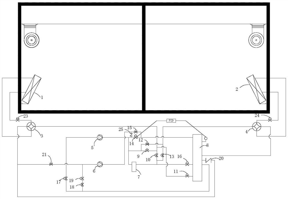
[0044] figure 1 It is a schematic diagram of the overall structure of the energy-saving enthalpy difference laboratory heat exchange system with switchable modes in the present invention.

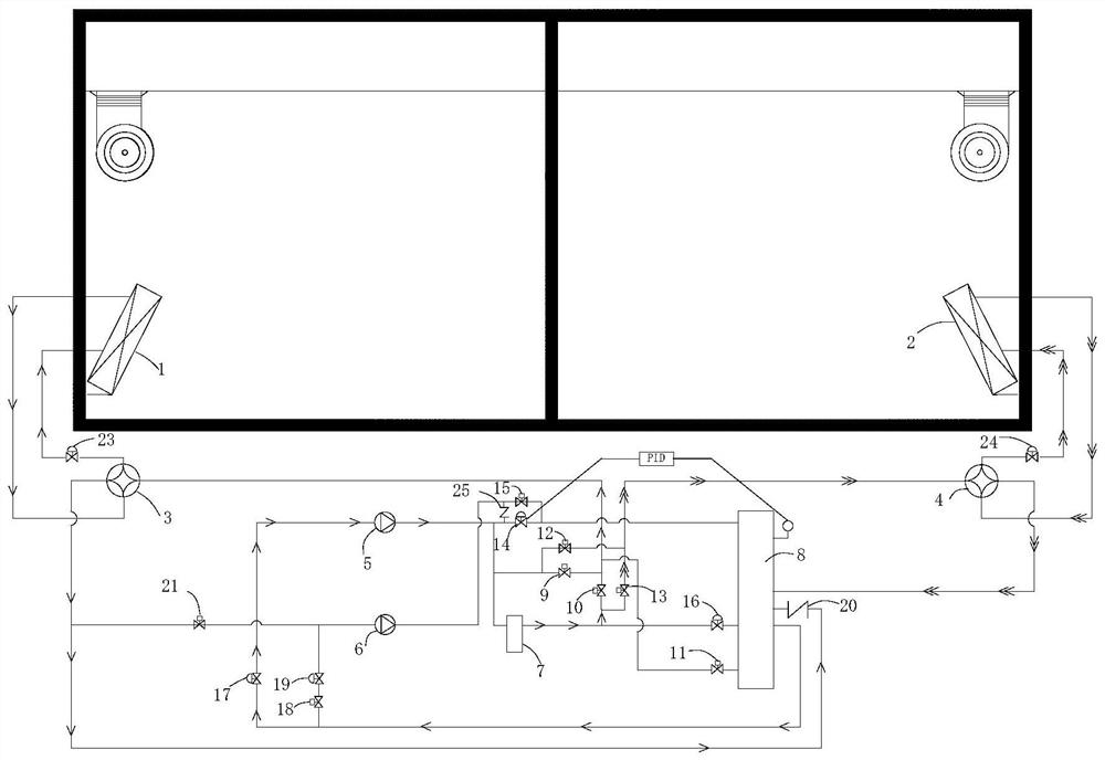
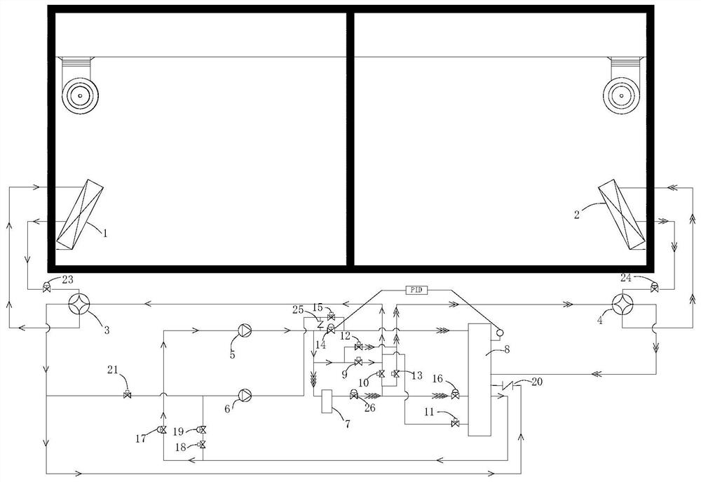
[0045] Such as figure 1 As shown, a switchable energy-saving enthalpy difference laboratory heat exchange system includes a first heat exchanger 1, a second heat exchanger 2, a first switch assembly, a second switch assembly, a third switch assembly, and a first switch assembly. Four switch assemblies, the first compressor 5, the second compressor 6, the condenser 7, the pressure regulating assembly and the fluorine barrel 8, wherein: the first compressor 5, the condenser 7 and the fluorine barrel 8 are connected in sequence to form a first cycle, The second compressor 6, the condenser 7 and the fluorine barrel 8 are circularly connected in turn to form the second cycle, both the first cycle and the second cycle can be used for the refrigerant condensation cycle, and the fluorine barrel 8 ...


PUM


Abstract

The invention discloses an energy-saving enthalpy difference laboratory heat exchange system capable of switching modes. The energy-saving enthalpy difference laboratory heat exchange system comprises a first heat exchanger, a second heat exchanger, a first switch assembly, a second switch assembly, a third switch assembly, a fourth switch assembly, a first compressor, a second compressor, a condenser, a pressure adjusting assembly and a fluorine barrel, wherein the first compressor, the condenser and the fluorine barrel are sequentially circulated to form a first circulation; the second compressor, the condenser and the fluorine barrel are sequentially circulated to form a second circulation; the first heat exchanger can be used for accessing and outputting a refrigerant at different positions of the first circulation or the second circulation through the first switch assembly; the second heat exchanger can be used for accessing and outputting the refrigerant at different positions of the first circulation or the second circulation through the second switch assembly; the second compressor can be communicated with an outlet of the fluorine barrel or an outlet of the first heat exchanger through the third switch assembly; the second compressor can be communicated with an inlet of the condenser or an inlet of the fluorine barrel through the fourth switch assembly; the pressure adjusting assembly can be used for adjusting the pressure of the fluorine barrel.

Description

technical field [0001] The invention relates to the field of refrigeration systems, in particular to a switchable mode energy-saving enthalpy difference laboratory heat exchange system. Background technique [0002] In the existing air-conditioning laboratory, the indoor and outdoor are generally equipped with independent refrigeration systems, which can be used to control the temperature of the laboratory. [0003] But the existing refrigeration system also has the following disadvantages: [0004] 1) Because the load of the air-conditioning laboratory has the characteristics of a heat pump, that is, when one side is in a cooling state, the other side must be in a heating state. Therefore, the cooling machines in both working conditions often do not need to reach the maximum capacity at the same time. Therefore, there will always be a part of the cold machine in an idle state and cannot be fully utilized. [0005] 2) Most of the chillers are operated by manual start-stop...

Claims


Application Information

Patent Timeline
Patent Type & Authority Applications(China)
IPC IPC(8): F25B39/00F25B41/40F25B41/20F25B13/00F25B49/02
CPCF25B39/00F25B41/40F25B41/20F25B13/00F25B49/022
Inventor 罗祥坤吉常斌刘凯陆考灵
Owner 广州兰石技术开发有限公司
Learn More