Ergonomic office chair
An ergonomic, office chair technology, applied in chairs, chairs with vertically adjustable seats, stools, etc., can solve the problems of easy bending of the back of the human body, strain on the waist of the human body, and the office chair cannot support the waist of the human body.
- Summary
- Abstract
- Description
- Claims
- Application Information
AI Technical Summary
Problems solved by technology
Method used
Image
Examples
Embodiment 1
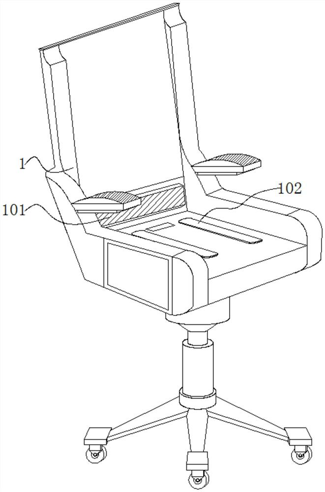
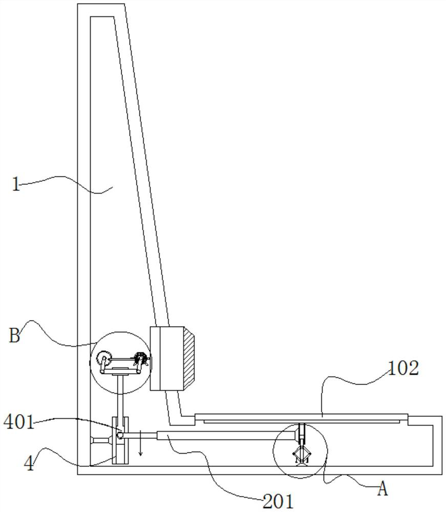
[0030] Embodiment 1: An ergonomic office chair, including a chair body 1, a backrest 101 and a seat cushion 102 slide on the inner side of the chair body 1, and a transmission mechanism that can automatically adjust the position of the backrest 101 is provided on the inner side of the chair body 1;
[0031] Wherein: the human body sits on the upper end of the cushion 102, the cushion 102 is squeezed downward, and then the cushion 102 is squeezed to the upper end of the transmission mechanism, and the transmission mechanism drives the backrest 101 to adjust the position, by continuously squeezing the upper end of the cushion 102 up and down, the backrest 101 can continuously Sliding horizontally, so that the backrest 101 can adjust the supporting distance from the back of the human body according to the needs of the human body;
[0032] Transmission mechanism comprises slide bar 2, push rod 201, track 4, slide block 401, raised bar 402, connecting rod 5, rotating ball 501, first...
Embodiment 2
[0038] Embodiment 2: with reference to instruction manual Figure 5 and 6 , The difference between Embodiment 2 and Embodiment 1 is that the transmission mechanism includes a disc 6, a swash plate 601, a gear plate 602, a squeeze plate 603, a second swing rod 7, a rotating disc 7, a limit rod 702, and the disc 6 Rotating on the outer side of the gear 503, the gear piece 602 surrounds the inner side of the disc 6, the swash plate 601 is inlaid on one side of the disc 6, the extrusion plate 603 surrounds the outer side of the disc 6, and the second swing rod 7 swings on the connecting On the other side of the rod 5, the rotating disk 701 rotates on one side of the second swing rod 7, and the limit rod 702 rotates on one side of the rotating disk 701;
[0039]The disk 6 is arranged in a ring shape, the surface of the disk 6 is embedded with a groove, the groove is arranged in a ring shape, the swash plate 601 is arranged inside the groove, and one end of the limit rod 702 slides...
Embodiment 3
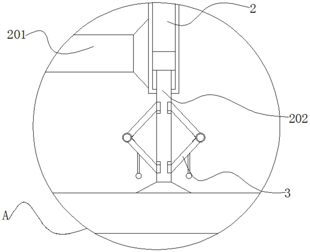
[0046] Embodiment 3: with reference to instruction manual image 3 The difference between Embodiment 3 and Embodiments 1 and 2 is that the transmission mechanism includes a support rod 202, a bracket 3, a rotating shaft 301, a steel wire bar 302 and a weight 303. Folding and sliding on both sides of the support rod 202, the rotating shaft 301 is hinged on the inner side of the bracket 3, the steel wire bar 302 swings on one side of the rotating shaft 301, and the weight 303 is installed on the lower end of the bracket 3;
[0047] The support rod 202 is embedded with grooves on both sides of the bracket 3, the bracket 3 slides vertically inside the groove, and the bracket 3 is arranged in a horizontal "eight" shape, and the bracket 3 and the rotating shaft 301 swing at 5-35°;
[0048] When the slide bar 2 slides downward, both sides of the lower end of the slide bar 2 are squeezed to the upper end of the bracket 3, and the upper end of the bracket 3 swings at an angle through t...
PUM
 Abstract
Description
Claims
Application Information
 - Generate Ideas
- Intellectual Property
- Life Sciences
- Materials
- Tech Scout
- Unparalleled Data Quality
- Higher Quality Content
- 60% Fewer Hallucinations
Browse by: Latest US Patents, China's latest patents, Technical Efficacy Thesaurus, Application Domain, Technology Topic, Popular Technical Reports.
© 2025 PatSnap. All rights reserved.Legal|Privacy policy|Modern Slavery Act Transparency Statement|Sitemap|About US| Contact US: help@patsnap.com


