
Anaerobic wastewater treatment device

A technology of wastewater treatment and anaerobic tower, applied in anaerobic digestion treatment, biological water/sewage treatment, water/sludge/sewage treatment, etc. The problems of low sewage treatment efficiency, etc., achieve the effect of avoiding excessive changes in the water inlet speed, facilitating adjustment, and preventing the water outlet speed from changing.

Pending Publication Date: 2022-01-07
HANGZHOU XINGYUAN FILTER TECH +1
View PDF4 Cites 0 Cited by
  • Summary
  • Abstract
  • Description
  • Claims
  • Application Information

AI Technical Summary

Problems solved by technology

[0005] The purpose of the present invention is to provide an anaerobic wastewater treatment device, which is used to solve the problem that it is difficult to adjust the water outlet speed to the best state, and the outflowing sewage and sludge cannot be fully mixed, resulting in low reactor sewage treatment efficiency. question

Method used


Image

  • Anaerobic wastewater treatment device
  • Anaerobic wastewater treatment device
  • Anaerobic wastewater treatment device

Examples


Embodiment Construction

[0024] The present invention will be described in detail below in conjunction with the drawings and specific embodiments. It should be noted that in the drawings or descriptions, similar or identical parts use the same figure numbers, and implementations that are not shown or described in the drawings The method is a form known to those of ordinary skill in the art. In addition, the directional terms mentioned in the embodiments, such as "upper", "lower", "top", "bottom", "left", "right", "front", "rear", etc., are only for reference to the accompanying drawings. The directions are not intended to limit the protection scope of the present invention.

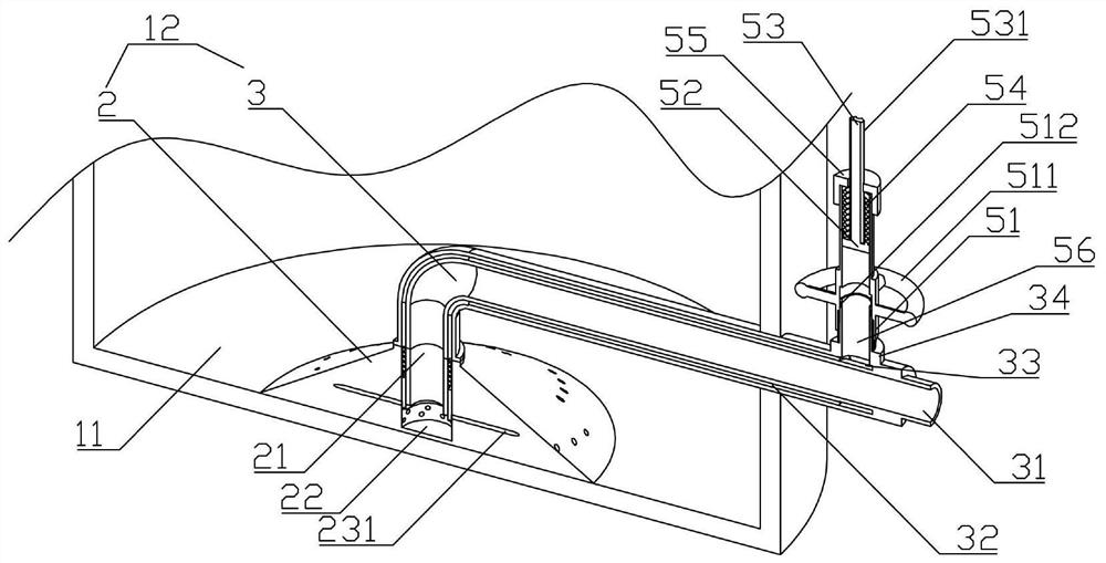
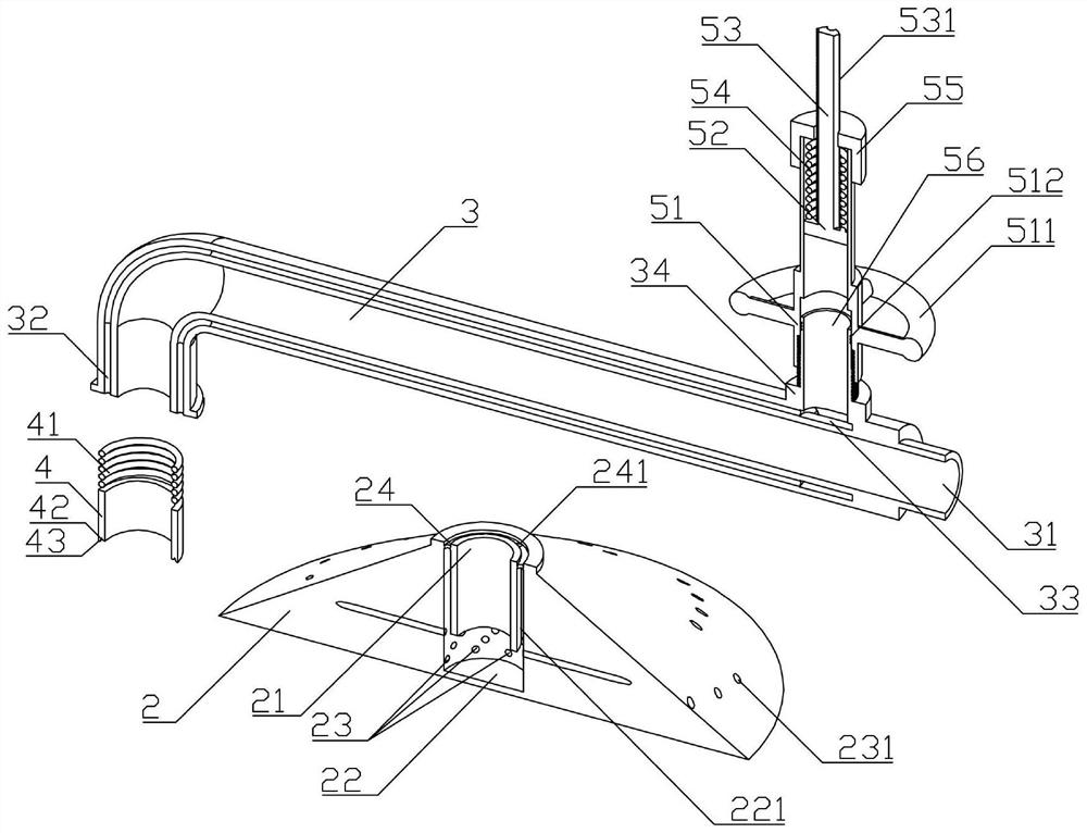
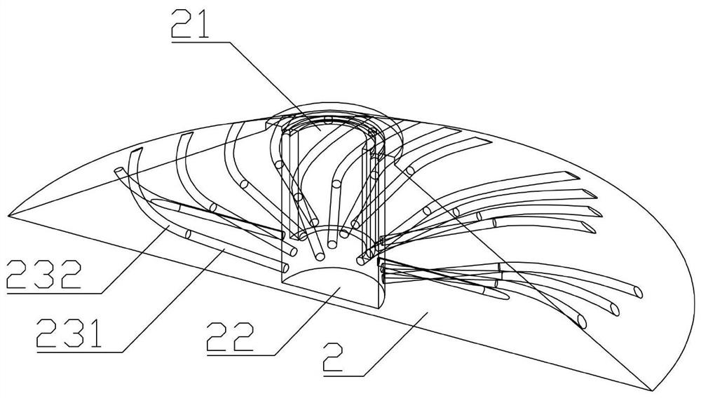
[0025] Such as Figure 1 ~ Figure 3 As shown, a kind of anaerobic wastewater treatment device of the present invention comprises anaerobic tower 11, and the inner bottom of anaerobic tower 11 is fixedly installed with swirl water distributor 12, and swirl water distributor 12 comprises cone 2 and connecting pipe 3, The cone 2 i...


PUM


Abstract

The invention belongs to the technical field of sewage treatment, and particularly relates to an anaerobic wastewater treatment device which comprises an anaerobic tower, a rotational flow water distributor is arranged at the inner bottom of the anaerobic tower and comprises a cone and a connecting pipeline, a water inlet is formed in the top of the cone, and the connecting pipeline penetrates through the side wall of the anaerobic tower and is in sealed connection with the water inlet. A water collecting cavity is formed in the cone, a plurality of water distributing layers are arranged in the cone in the vertical direction, a first annular groove is formed in the top of the water collecting cavity, an annular plug body and a first spring are arranged in the first annular groove in a sliding mode, a second annular groove is formed in the top of the cone, and a plurality of adjusting channels are formed in the side wall of the connecting pipeline; a first connector and a second connector are arranged at the free end of the connecting pipeline, and an adjusting assembly is arranged on the second connector. The problems that in the prior art, the water outlet speed is difficult to adjust to the optimal state, and flowing-out sewage and sludge cannot be fully mixed, so that the sewage treatment efficiency of a reactor is low are solved.

Description

technical field [0001] The invention belongs to the technical field of sewage treatment, and in particular relates to an anaerobic waste water treatment device. Background technique [0002] Upflow sludge bed-filter (UBF for short) is a new composite anaerobic fluidized bed reactor developed by Canadian Guiot on the basis of anaerobic filter and upflow anaerobic sludge bed. UBF reactor usually includes Water distribution area, granular sludge area, soft packing area, filter layer and three-phase separator and other parts. [0003] Most of the existing water distribution areas are equipped with swirl water distributors. Through the swirl water distributors, the sewage flowing out of the water distribution outlet forms a swirl water distribution in the granular sludge area at the bottom of the reactor, so that the sewage can be mixed with the sludge. Improve the treatment efficiency of the anaerobic reactor. [0004] However, at present, the water outlet flow rate of the swi...

Claims


Application Information

Patent Timeline
IPC IPC(8): C02F3/28
CPCC02F3/2866C02F1/006C02F3/006Y02E50/30
Inventor 许生军徐鹏苏园园戴佳亮李洁
Owner HANGZHOU XINGYUAN FILTER TECH
Learn More