
Dual-power-supply dual-frequency-band power line carrier communication method

A power carrier communication, dual-band technology, applied in the direction of electrical components, distribution line transmission system, wired transmission system, etc. Play a role and other issues to achieve the effect of ensuring power utilization, improving power utilization, and improving efficiency

Active Publication Date: 2022-01-04
航天中电(重庆)微电子有限公司
View PDF5 Cites 0 Cited by
  • Summary
  • Abstract
  • Description
  • Claims
  • Application Information

AI Technical Summary

Problems solved by technology

However, on the one hand, each station needs enough time to send data, so when the number of stations is large enough, it is difficult to divide a beacon period into enough time slots, so that multiple beacon periods are required to realize the communication of all stations. The uploading of information and data leads to low efficiency of information and data communication in the power communication network system; on the other hand, the existing power carrier communication is mainly aimed at the communication network of the main power supply of the communication power system, and the secondary power supply is difficult to play in power carrier communication as a backup power supply. effect, resulting in low power utilization of the communication power system

Method used


Image

  • Dual-power-supply dual-frequency-band power line carrier communication method
  • Dual-power-supply dual-frequency-band power line carrier communication method
  • Dual-power-supply dual-frequency-band power line carrier communication method

Examples


Embodiment

[0027] Example discloses a dual-band dual-carrier communication method for electric power supply of the present embodiment.

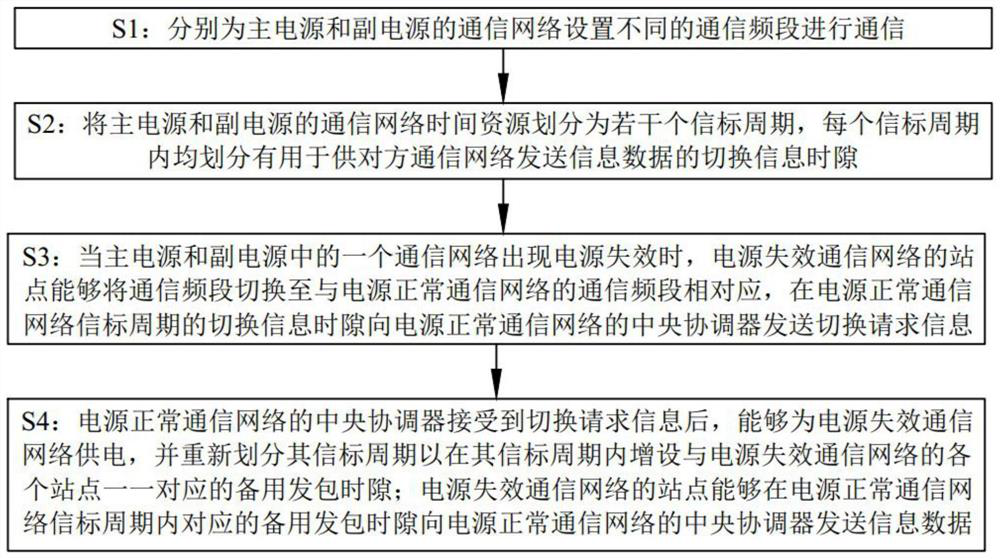
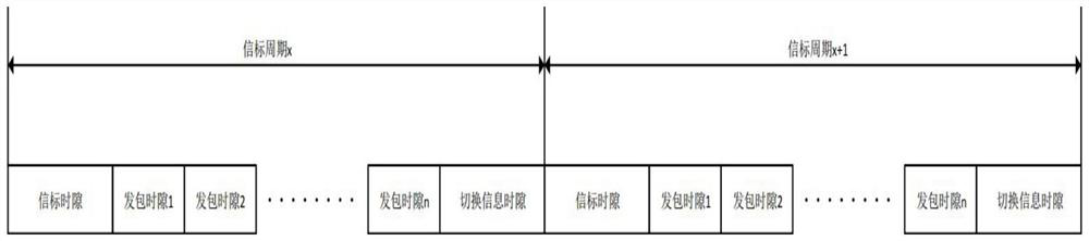
[0028] like figure 1 Shown, a dual-band dual-power power line carrier communication method, comprising:

[0029] S1: respectively based communication network and the sub-power supply provided different communication frequency bands for communication. Specifically, the main power of the communication network communications band is 2MHz ~ 10MHz; sub power communications band communication network is 20MHz ~ 28MHz. A communication network consistent spectral power mains and sub-bandwidth. Frequency range chip supports of the present invention is 0-37M, taking into account the following 2M electrical interference is serious, the use of spectrum resources in more than 2M communications band division. Two band communication network can be provided to ensure that the transmission rate and stability of the communications bands at the same time, try to make the two ...


PUM


Abstract

The invention particularly relates to a dual-power-supply dual-frequency-band power line carrier communication method. The method comprises the following steps: setting different communication frequency bands for communication networks of a main power supply and an auxiliary power supply; dividing a communication network time resource into a plurality of beacon periods, and dividing a switching information time slot in each beacon period; when a power failure occurs in one communication network, a station of the communication network with the power failure being capable of switching a communication frequency band and sending switching request information to a central coordinator of a communication network with a normal power supply; after receiving the switching request information, the central coordinator of the communication network with the normal power supply being capable of supplying power to the communication network with the failure power supply, and a standby packet sending time slot being additionally arranged in a beacon period of the communication network with the failure power supply; and the station of the power failure communication network sending information data to the central coordinator of the power normal communication network through the standby packet sending time slot. The power line carrier communication method can effectively avoid signal interference between communication networks of the main power supply and the auxiliary power supply and can realize power supply switching of the main power supply and the auxiliary power supply.

Description

Technical field [0001] The present invention relates to the field of power line carrier technology, particularly to a dual-band dual-power power line carrier communication method. Background technique [0002] Communication power supply system for the communication equipment and ancillary facilities to provide uninterrupted power supply, electric power infrastructure is an important communication network system, is one of the basic elements of protection of the safe operation of the power grid. Existing communication system generally includes a backup power supply sub-main power supply and as a daily work. [0003] In the communication network system is similar to the power train, unmanned aircraft, highly integrated, it is generally realized using a separate communication line transmission of information data, some of the weight gain of a communication line even hundreds of meters (a few hundred pounds), which is not conducive to power communication network system integration an...

Claims


Application Information

Patent Timeline
Patent Type & Authority Applications(China)
IPC IPC(8): H04B3/54
CPCH04B3/544H04B3/54
Inventor 邢双进陈咏诗
Owner 航天中电(重庆)微电子有限公司
Learn More