
Imbricated photovoltaic module supporting frame

A photovoltaic module and support frame technology, applied in the support structure of photovoltaic modules, photovoltaic modules, photovoltaic power generation and other directions, can solve the problems of complex structure, unfavorable laying and use of photovoltaic modules, etc., to improve utilization efficiency, simple and practical structure, improve The effect of flexibility

Pending Publication Date: 2022-01-04
JAYU DOOR & WINDOW & CURTAIN WALL XUZHOU CO LTD
View PDF0 Cites 0 Cited by
  • Summary
  • Abstract
  • Description
  • Claims
  • Application Information

AI Technical Summary

Problems solved by technology

[0002] A photovoltaic module is a photovoltaic device that can convert solar energy into electrical energy. It is the core part of the solar power generation system. After converting solar energy into electrical energy, the photovoltaic module will send the electrical energy to the battery for storage, or drive the load to work. Since photovoltaic modules need solar energy to work, in order to improve the utilization efficiency of solar energy as much as possible, it is necessary to erect a support frame at the bottom of the photovoltaic module, and the support frame provides support for the photovoltaic module, but the current structure of the support frame cannot be flexible. Multi-angle rotation to improve the utilization efficiency of solar energy, and the structure is too complicated, which is not conducive to the laying and use of photovoltaic modules

Method used


Image

  • Imbricated photovoltaic module supporting frame
  • Imbricated photovoltaic module supporting frame
  • Imbricated photovoltaic module supporting frame

Examples


Embodiment 1

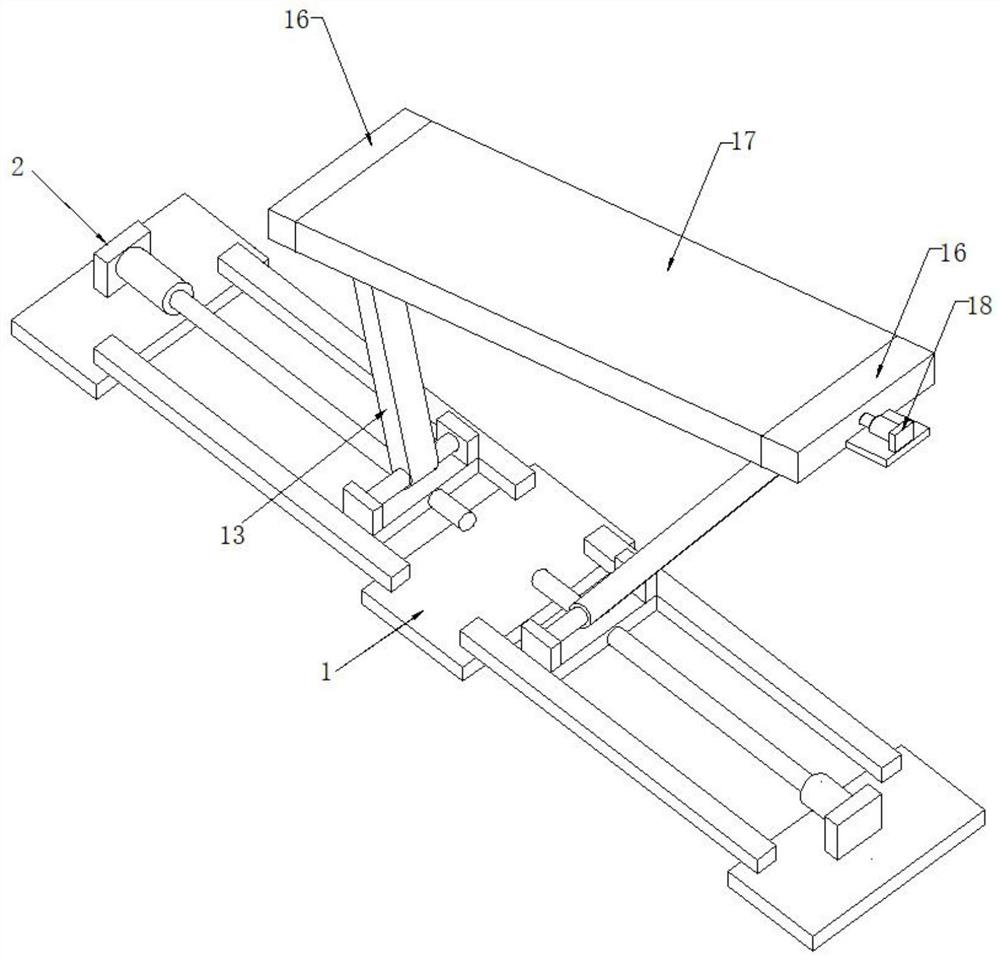
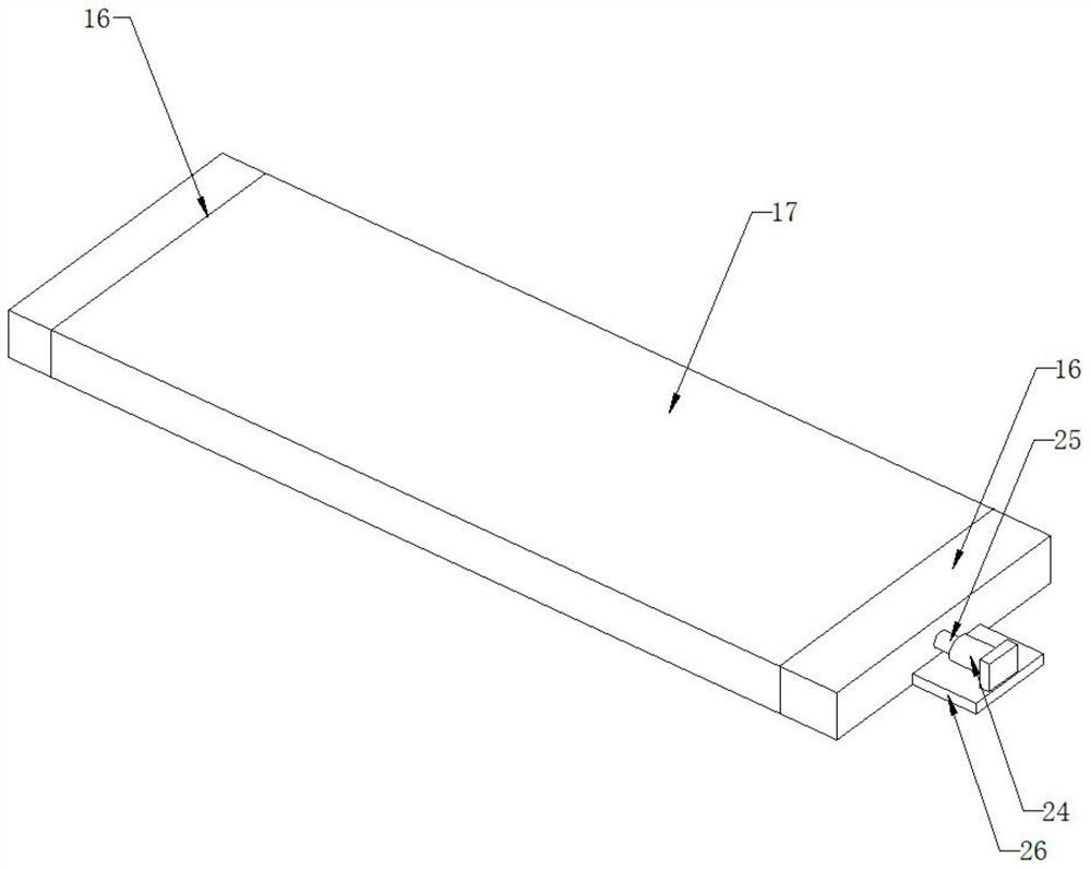
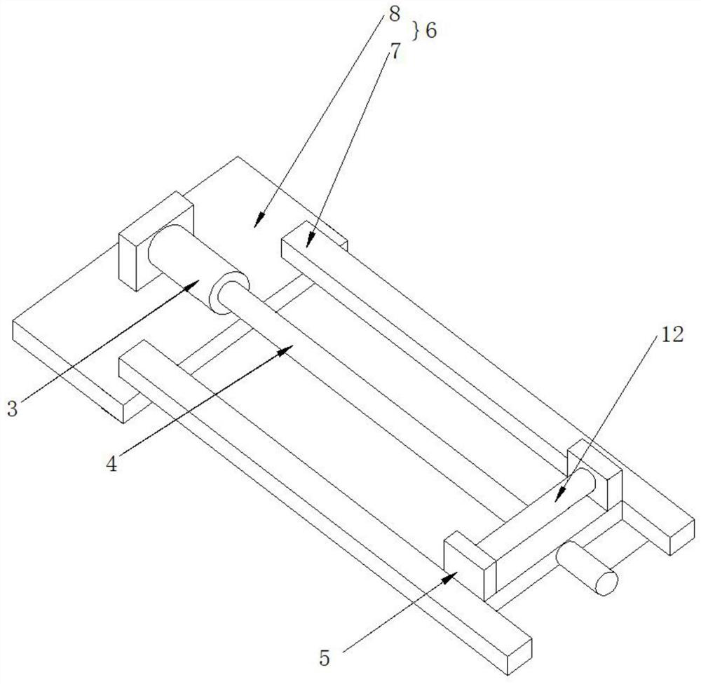
[0028] Such as Figure 1-5 As shown, the present invention provides a shingled photovoltaic module support frame, including a base 1, the base 1 is composed of two adjustment structures 2, and the adjustment structure 2 includes a servo motor 3, a screw 4, a moving slide 5 and a support base 6, The support base 6 is composed of two longitudinal supports 7 and two transverse support plates 8, the inner side of the longitudinal support 7 is provided with a screw 4, one end of the screw 4 is connected with a servo motor 3, and the other end of the screw 4 is connected with a moving slide 5, The screw rod 4 and the moving slide 5 form a screw nut structure, the inside of the moving slide 5 is equipped with a first fixed shaft 12, the outside of the first fixed shaft 12 is sleeved with a connecting plate 13, and one end of the connecting plate 13 is sleeved with a second Two fixed shafts 14, the two ends of the second fixed shaft 14 are connected with a fixed seat 15, the top of th...


PUM


Abstract

The invention discloses an imbricated photovoltaic module supporting frame, and the supporting frame comprises a base; the base is composed of two adjusting structures, each adjusting structure comprises a servo motor, a screw, a movable sliding seat and a supporting seat, the supporting seat is composed of two longitudinal supports and two transverse supporting plates, the screw is arranged on the inner sides of the longitudinal supports, one end of the screw is connected with the servo motor, the other end of the screw rod is connected with a movable sliding seat, the screw rod and the movable sliding seat form a lead screw nut structure, a first fixing shaft is installed on the inner side of the movable sliding seat, the outer side of the first fixing shaft is sleeved with a connecting plate, one end of the connecting plate is sleeved with a second fixing shaft, the two ends of the second fixing shaft are connected with fixed seats, and the tops of the fixed seats are connected with supporting frames; an overturning plate is arranged between the supporting frames, and a rotating device is installed on one side of each supporting frame. According to the invention, the supporting frames at the two ends are driven by the adjusting structure to carry out multidirectional and multi-angle conversion, so the longitudinal rotation of the photovoltaic module is realized, and the utilization efficiency of the photovoltaic module is improved.

Description

technical field [0001] The invention relates to the technical field of photovoltaic equipment, in particular to a shingled photovoltaic module support frame. Background technique [0002] A photovoltaic module is a photovoltaic device that can convert solar energy into electrical energy. It is the core part of the solar power generation system. After converting solar energy into electrical energy, the photovoltaic module will send the electrical energy to the battery for storage, or drive the load to work. Since photovoltaic modules need solar energy to work, in order to improve the utilization efficiency of solar energy as much as possible, it is necessary to erect a support frame at the bottom of the photovoltaic module, and the support frame provides support for the photovoltaic module, but the current structure of the support frame cannot be flexible. The multi-angle rotation can improve the utilization efficiency of solar energy, and the structure is too complicated, wh...

Claims


Application Information

Patent Timeline
Patent Type & Authority Applications(China)
IPC IPC(8): H02S20/30F24S30/48
CPCH02S20/30F24S30/48Y02E10/47Y02E10/50
Inventor 陈志荣马小彬
Owner JAYU DOOR & WINDOW & CURTAIN WALL XUZHOU CO LTD
Learn More