Control method of switching power supply and switching power supply

A technology of switching power supply and control method, applied in the field of power supply, can solve the problems of increasing the hardware cost of switching power supply, increasing the difficulty of power supply control, complex switching power supply circuit structure, etc., and achieving the effects of improving EMI characteristics, easy control, and large switching loss.

Active Publication Date: 2022-01-04
MIPTECH LTD
View PDF4 Cites 1 Cited by
  • Summary
  • Abstract
  • Description
  • Claims
  • Application Information

AI Technical Summary

Problems solved by technology

However, compared with the non-isolated switching power supply of the basic structure, the non-isolated switching power supply that can realize ZVS needs to add several key control links and the corresponding hardware circuit structure. The circuit structure of the switching power supply based on the ZVS design idea tends to be complicated. It not only increases the hardware cost of the switching power supply, but also increases the difficulty of controlling the power supply

Method used


Image

  • Control method of switching power supply and switching power supply
  • Control method of switching power supply and switching power supply
  • Control method of switching power supply and switching power supply

Examples


Embodiment Construction

[0041] The present invention will be further described in detail below in conjunction with the accompanying drawings and embodiments. It should be understood that the specific embodiments described here are only used to explain the present invention, but not to limit the present invention. In addition, it should be noted that, for the convenience of description, only some structures related to the present invention are shown in the drawings but not all structures.

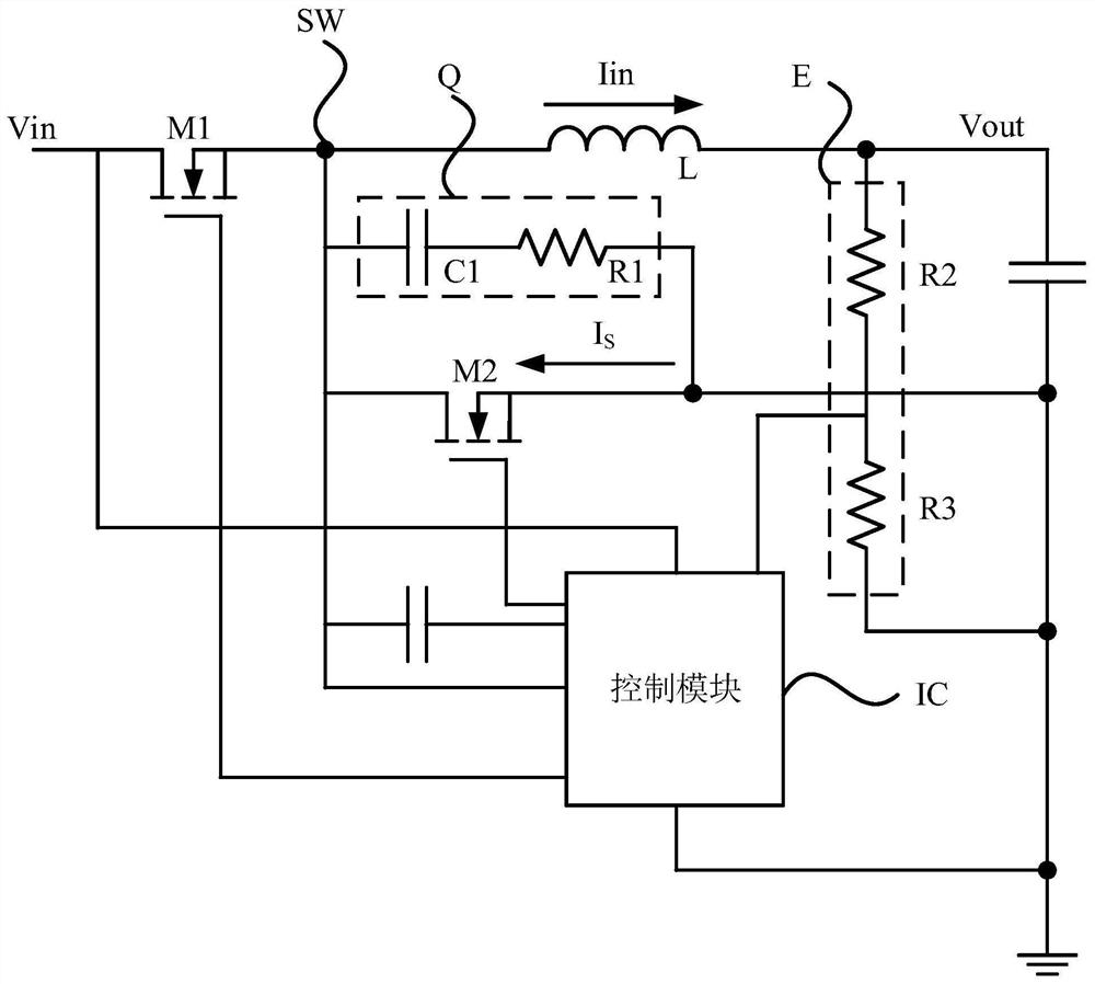
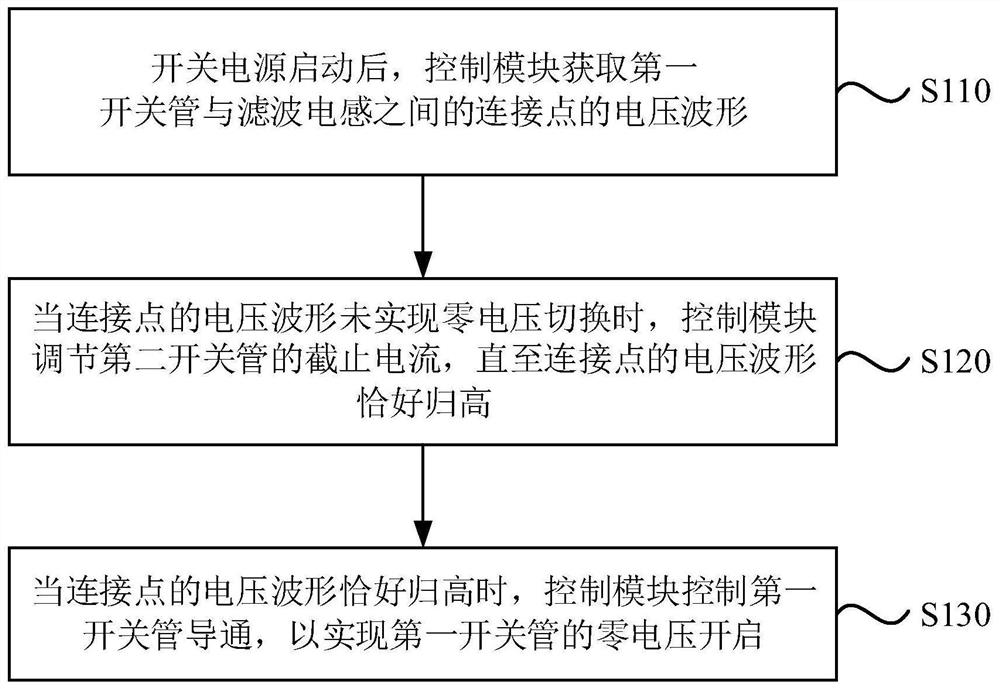
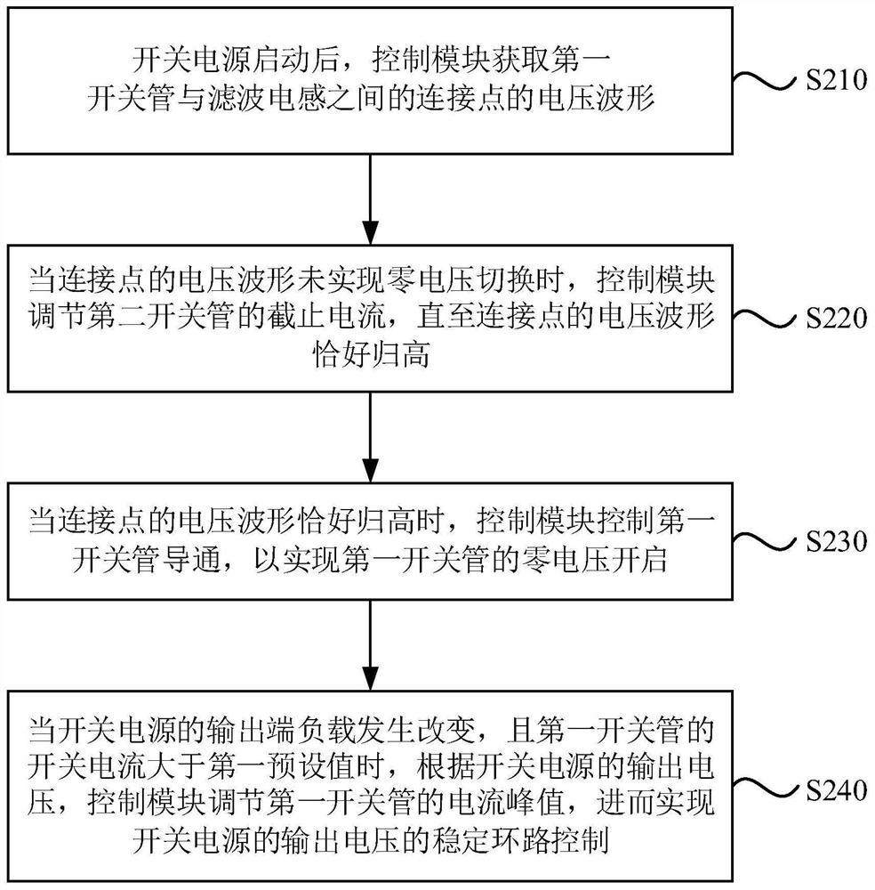
[0042] figure 1 It is a schematic structural diagram of a switching power supply provided by an embodiment of the present invention, figure 2 It is a flowchart of a control method for a switching power supply provided by an embodiment of the present invention. The embodiment of the present invention can be applied to the power supply scene of any device with a non-isolated synchronous switching power supply structure with basic architectures such as buck, boost, and buck-boost. The control method can be but not ...


PUM


Abstract

The embodiment of the invention discloses a control method of a switching power supply and the switching power supply. The control method comprises the steps that after the switching power supply is started, the control module obtains a voltage waveform of a connection point between the first switching tube and the filter inductor; when the voltage waveform of the connection point does not realize zero voltage switching, the control module adjusts the cut-off current of the second switching tube until the voltage waveform of the connection point is exactly increased; and when the voltage waveform of the connection point is exactly increased, the control module controls the first switch tube to be switched on so as to realize zero-voltage switching-on of the first switch tube. According to the embodiment of the invention, on the premise of not increasing the hardware cost of the switching power supply, the switching loss of the switching power supply is reduced, and the EMI characteristic of the switching power supply is effectively improved.

Description

technical field [0001] Embodiments of the present invention relate to the technical field of power supplies, and in particular, to a control method of a switching power supply and a switching power supply. Background technique [0002] In the field of power supply, non-isolated switching power supply has many advantages such as simple circuit, low cost and low space requirement. Non-isolated switching power supply based on basic architectures such as buck, boost, and buck-boost It is widely used in the power supply process of electrical equipment. [0003] At present, the non-isolated switching power supply of the existing basic structure has excessive switching loss, low efficiency, and high degree of Electromagnetic Interference (EMI), which severely limits the increase of the switching frequency of the power supply and hinders the miniaturization of the switching power supply. Based on this, a non-isolated switching power supply design capable of realizing zero voltage s...

Claims


Application Information

Patent Timeline
Patent Type & Authority Applications(China)
IPC IPC(8): H02M1/08H02M1/44H02M3/158
CPCH02M1/083H02M1/44H02M3/158Y02B70/10
Inventor 不公告发明人
Owner MIPTECH LTD
Why Eureka
Try Eureka