Double-sided display device and manufacturing method thereof

A double-sided display device and double-sided display technology, which can be used in instruments, nonlinear optics, optics, etc., can solve the problems of unfavorable energy saving and emission reduction, strong dependence on reflective LCD screens, and high power consumption of displays

Pending Publication Date: 2022-01-04
HKC CORP LTD
View PDF12 Cites 0 Cited by
  • Summary
  • Abstract
  • Description
  • Claims
  • Application Information

AI Technical Summary

Problems solved by technology

[0002] In the traditional double-sided liquid crystal display, due to the use of transmissive liquid crystal panels, two liquid crystal displays and corresponding backlights need to be applied, so the thickness is relatively thick and the power consumption is high, especially when displaying in bright outdoors. The display screen requires high brightness to see clearly, so the backlight of the display needs to have a high brightness, which will lead to high power consumption of the display, which is not conducive to energy saving and emission reduction; and the reflective display screen is located at the bottom of the liquid crystal display panel. It is installed with reflective material to replace the luminescent material of the transmissive display screen. When the ambient light is sufficient, it uses the light reflected by the mirror to illuminate the screen. The reflective LCD screen is more dependent on ambient light.

Method used


Image

  • Double-sided display device and manufacturing method thereof
  • Double-sided display device and manufacturing method thereof
  • Double-sided display device and manufacturing method thereof

Examples


no. 1 example

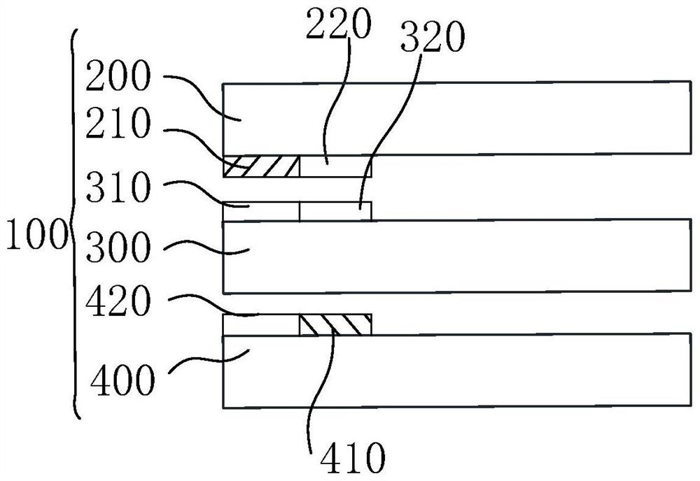
[0040] figure 1 is a schematic diagram of a double-sided display device provided in the first embodiment of the present application, as shown in figure 1 As shown, a double-sided display device 100 includes a first substrate 200, a second substrate 300, a backlight module 400, and a liquid crystal layer 500, and a liquid crystal layer is arranged between the first substrate 200 and the second substrate 300 500, the side of the second substrate 300 facing away from the first substrate 200 is provided with a backlight module 400, the first substrate 200 includes a reflective region 210 and a first transmissive region 220, the second substrate 300 Including the second transmission area 310 and the third transmission area 320, the backlight module 400 includes the backlight area 410 and the fourth transmission area 420; wherein, the reflection area 210 and the second transmission area 310 are set correspondingly, the first The transmission area 220 is disposed corresponding to th...

no. 2 example

[0055] Figure 5 is a schematic diagram of a first substrate and a second substrate provided in the second embodiment of the present application, as shown in Figure 5 As shown, the difference between this embodiment and the first embodiment is that the reflective regions 210 are arranged in rows along the data line direction to obtain the reflective region rows, and the first transmissive regions 220 are arranged in rows along the data line direction to obtain the second A row of transmissive regions, the row of reflective regions and the row of first transmissive regions are arranged in row offset; the row of second transmissive regions 310 is arranged in rows along the direction of the data line to obtain the row of second transmissive regions, and the row of the third transmissive regions 320 are arranged in rows along the data line direction to obtain the third transmission area row, and the second transmission area row and the third transmission area row are arranged in ...

no. 3 example

[0059] Image 6 It is a schematic diagram of a first substrate and a second substrate provided in the third embodiment of the present application, as shown in Image 6 As shown, different from the first and second embodiments, each of the reflective regions 210 is provided with P first pixel electrodes 212, and each of the second transmissive regions 310 is provided with Q second pixel electrodes. Color resistance, the first pixel electrode 212 is set corresponding to the second sub-color resistance; each of the third transmission regions 320 is provided with Q second pixel electrodes 322, and each of the first transmission regions 220 There are P first sub-color resistances disposed therein, and the second pixel electrode 322 is disposed correspondingly to the first sub-color resistances; wherein, P≠Q.

[0060] In this way, in the direction along the data line, the resolution of the region where the number of pixel electrodes is larger than the number of color resistors is h...


PUM


Abstract

The invention discloses a double-sided display device and a manufacturing method thereof. The double-sided display device comprises a first substrate, a second substrate, a backlight module and a liquid crystal layer; the liquid crystal layer is arranged between the first substrate and the second substrate; the backlight module is arranged on the side, opposite to the first substrate, of the second substrate; and the first substrate comprises a reflection area and a first transmission area; the second substrate comprises a second transmission area and a third transmission area; and the backlight module comprises a backlight area and a fourth transmission area; the reflection area and the second transmission area are correspondingly arranged; the first transmission area and the third transmission area are correspondingly arranged; the backlight area and the second transmission area are correspondingly arranged; and the fourth transmission area and the third transmission area are correspondingly arranged. By means of the above design, double-sided display is achieved, one side is in a reflective display mode, and the other side is in a backlight display mode.

Description

technical field [0001] The present application relates to the field of display technology, in particular to a double-sided display device and a manufacturing method thereof. Background technique [0002] In the traditional double-sided liquid crystal display, due to the use of transmissive liquid crystal panels, two liquid crystal displays and corresponding backlights need to be applied, so the thickness is relatively thick and the power consumption is high, especially when displaying in bright outdoors. The display screen requires high brightness to see clearly, so the backlight of the display needs to have a high brightness, which will lead to high power consumption of the display, which is not conducive to energy saving and emission reduction; and the reflective display screen is located at the bottom of the liquid crystal display panel. It is installed with reflective material to replace the luminescent material of the transmissive display screen. When the ambient light ...

Claims


Application Information

Patent Timeline
IPC IPC(8): G02F1/1333G02F1/13357
CPCG02F1/133342G02F1/1336
Inventor 夏天宇袁海江
Owner HKC CORP LTD
Why Eureka
Try Eureka