
High-precision multi-azimuth inverse time seismic source imaging method based on elastic wave field decoupling

An imaging method and elastic wave technology, applied in seismology, seismic signal processing, measuring devices, etc., can solve the problem that the imaging results cannot correctly reflect the source rupture characteristics, and achieve the effect of high computing efficiency

Active Publication Date: 2022-01-04
CHINA UNIV OF PETROLEUM (EAST CHINA)
View PDF9 Cites 0 Cited by
  • Summary
  • Abstract
  • Description
  • Claims
  • Application Information

AI Technical Summary

Problems solved by technology

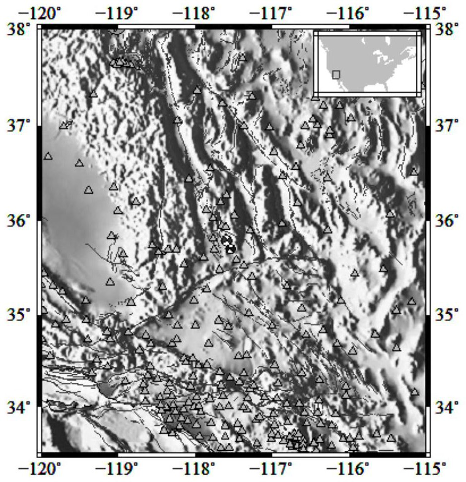
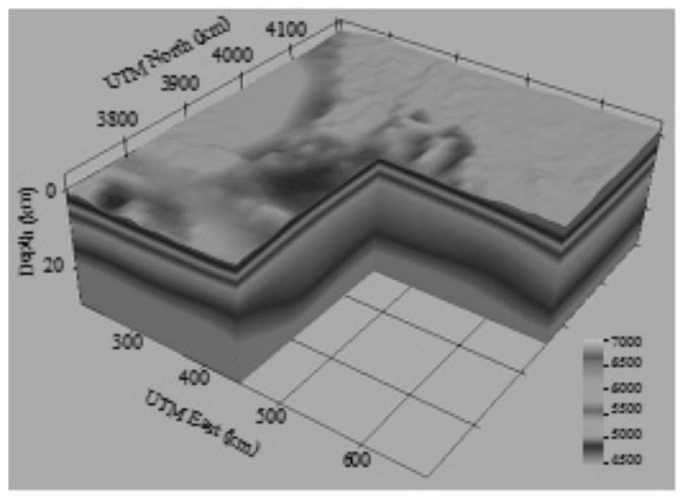
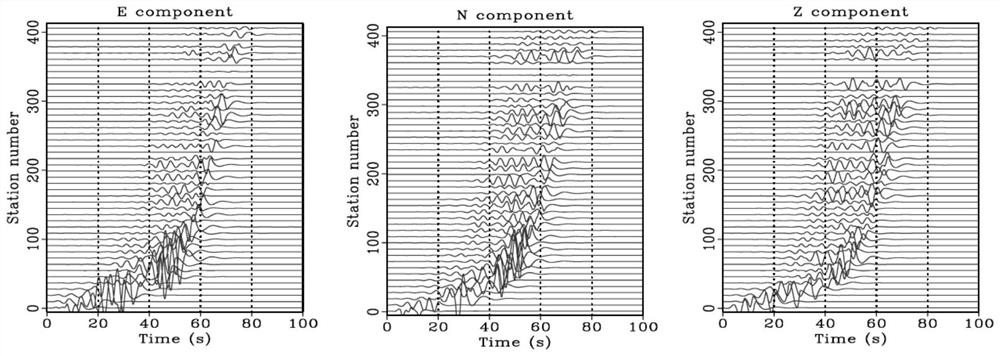
[0005] In order to solve the technical problem that the imaging results in the existing seismic source imaging methods cannot correctly reflect the rupture characteristics of the seismic source, the present invention discloses a high-precision multi-azimuth reverse-time seismic source imaging method based on elastic wave field decoupling. The seismic records observed by the azimuth network are used as boundary conditions. By solving the elastic wave equation, the backpropagation elastic wavefield is calculated, and the backpropagation wavefield is separated by vector Helmholtz decomposition. According to the traditional zero-delay mutual Related imaging conditions, the energy of the separated P-wave and S-wave wave fields are multiplied and summed in the local time window to obtain the distribution of rupture energy in the source area at this moment

Method used


Image

  • High-precision multi-azimuth inverse time seismic source imaging method based on elastic wave field decoupling
  • High-precision multi-azimuth inverse time seismic source imaging method based on elastic wave field decoupling
  • High-precision multi-azimuth inverse time seismic source imaging method based on elastic wave field decoupling

Examples


Embodiment Construction

[0047] The following will clearly and completely describe the technical solutions in the embodiments of the present invention with reference to the accompanying drawings in the embodiments of the present invention. Obviously, the described embodiments are only some of the embodiments of the present invention, not all of them. Based on the embodiments of the present invention, all other embodiments obtained by persons of ordinary skill in the art without making creative efforts belong to the protection scope of the present invention.

[0048]The conventional back-projection source imaging method mainly uses teleseismic data, and there are obvious artifacts of shifting with the change of the station network, so that the imaging results cannot correctly reflect the rupture characteristics of the source region. In order to obtain accurate near-seismic source rupture imaging results and suppress the migration artifacts in single-azimuth network imaging, the present invention disclos...


PUM


Abstract

The invention discloses a high-precision multi-azimuth inverse time seismic source imaging method based on elastic wave field decoupling, and relates to the technical field of geophysical seismic source imaging. According to the method, seismic records observed by a plurality of azimuth station networks are used as boundary conditions, a back propagation elastic wave field is calculated by solving an elastic wave equation, longitudinal and transverse wave field separation are carried out on the back propagation wave field by utilizing vector Helmholtz decomposition, and the energies of the separated P wave field and S wave field in a local time window are multiplied and summed according to the traditional zero-delay cross-correlation imaging condition to obtain the distribution of the fracture energy of the seismic source region at the moment. The longitudinal and transverse wave information and the multi-azimuth imaging condition are used, so that not only can the offset illusion be suppressed, but also the fracture characteristics of the seismic source region can be described more accurately; and a high-precision four-dimensional fracture imaging result is generated, propagation characteristics of energy at different depths can be finely described, and the method is of great importance for determining seismic source position distribution and researching underground hidden faults.

Description

technical field [0001] The invention relates to the technical field of geophysical seismic source imaging, in particular to a high-precision multi-azimuth reverse-time seismic source imaging method based on elastic wave field decoupling. Background technique [0002] At present, seismic source imaging is the key to study the mechanism of seismic source rupture and regional structure. The results of 4D seismic source imaging directly reflect the spatiotemporal evolution of the source region rupture process. Conventional source imaging methods include the source time function method and the direct waveform method. The former depends on the accuracy of the extracted source time function, while the latter requires the prior information of the fault to assume the fault model, making the accuracy of the source imaging result too dependent on the initial condition. In order to solve this problem, using the principle of reverse time migration imaging in exploration seismology, the ...

Claims


Application Information

Patent Timeline
Patent Type & Authority Applications(China)
IPC IPC(8): G01V1/30G01V1/34
CPCG01V1/303G01V1/345G01V2210/622Y02A90/30
Inventor 杨继东苏来源黄建平李振春
Owner CHINA UNIV OF PETROLEUM (EAST CHINA)
Learn More