
Low-noise narrow-linewidth Brillouin random fiber laser

A fiber laser, low-noise technology, used in lasers, phonon exciters, laser components, etc., can solve the problems of increasing system operation complexity, low cost performance, multi-mode resonance, etc., achieving good mode selection effect and high cost performance. , the effect of improving stability

Pending Publication Date: 2021-12-31
SHANDONG UNIV
View PDF7 Cites 0 Cited by
  • Summary
  • Abstract
  • Description
  • Claims
  • Application Information

AI Technical Summary

Problems solved by technology

[0005] However, whether it is a Brillouin random fiber laser with a semi-open ring cavity or a linear cavity, their laser output has relatively strong instability, which is due to the disturbance and random distributed feedback of the long fiber in the laser structure. Due to the randomly distributed cavity lengths generated, and in the output laser, there are mode-hopping phenomena and even multi-mode resonance phenomena due to strong mode competition; although some workers later used Faber interferometers, polarization-maintaining fibers, etc. To reduce the noise of the Brillouin random fiber laser output laser, but the method of adding the Faber interferometer requires fine adjustment of the interferometer, which increases the operational complexity of the system, and the commercial Faber interferometer is expensive, The cost performance is too low; the method of using polarization maintaining fiber only eliminates the instability of the laser output caused by the mismatch between the polarization state of the pump light and the Stokes light, but fails to completely eliminate the factors that make the laser output unstable

Method used


Image

  • Low-noise narrow-linewidth Brillouin random fiber laser
  • Low-noise narrow-linewidth Brillouin random fiber laser
  • Low-noise narrow-linewidth Brillouin random fiber laser

Examples


Embodiment Construction

[0029] The following will clearly and completely describe the technical solutions in the embodiments of the present invention with reference to the drawings in the embodiments of the present invention.

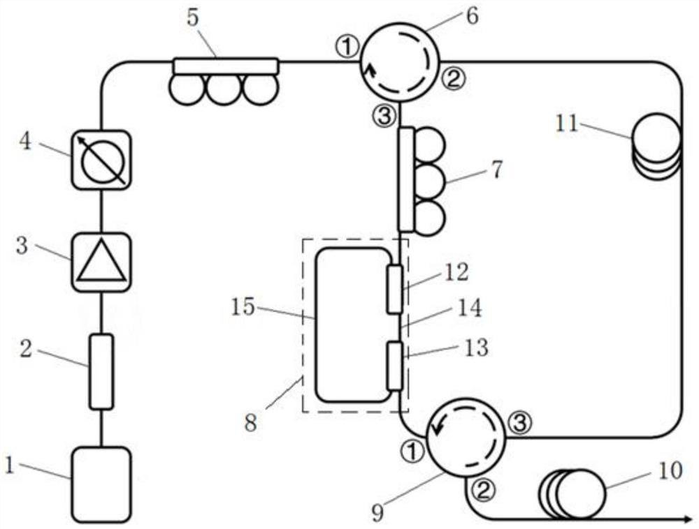
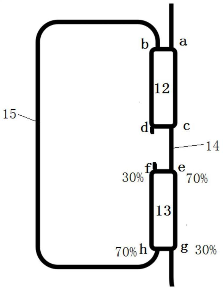
[0030] The invention provides a low-noise narrow-linewidth Brillouin random fiber laser, such as figure 1 As shown, it includes sequentially connected pump laser (Pump laser) 1, optical isolator (ISO) 2, erbium-doped fiber amplifier (EDFA) 3, tunable fiber attenuator (VOA) 4, first polarization controller (PC1 ) 5, the first fiber circulator (CIR1) 6, the second polarization controller (PC2) 7, the double coupler ring resonator (DCFRR) 8, the second fiber circulator (CIR2) 9 and the Rayleigh scattering fiber 10, The first polarization controller 5 and the second polarization controller 7 are respectively connected to port one (1) and port three (3) of the first optical fiber circulator 6, and the output end of the double coupler ring resonator 8 and the input end of the Raylei...


PUM

PropertyMeasurementUnit
wavelengthaaaaaaaaaa
lengthaaaaaaaaaa
lengthaaaaaaaaaa

Abstract

The invention discloses a low-noise narrow-linewidth Brillouin random fiber laser, and the laser comprises a pump laser, an optical isolator, an erbium-doped fiber amplifier, a tunable fiber attenuator, a first polarization controller, a first fiber circulator, a second polarization controller, a double-coupler ring resonator, a second fiber circulator and a Rayleigh scattering fiber which are connected in sequence. The first polarization controller and the second polarization controller are connected with a first port and a third port of the first optical fiber circulator respectively, and the output end of the double-coupler ring resonator and the input end of the Rayleigh scattering optical fiber are connected with a first port and a second port of the second optical fiber circulator respectively. A Brillouin gain optical fiber is connected between a second port of the first optical fiber circulator and a third port of the second optical fiber circulator, and the Brillouin random optical fiber laser can suppress mode competition in the laser, so that relative intensity noise and frequency noise output by random laser can be reduced, and the stability of output laser is improved.

Description

technical field [0001] The invention relates to the field of fiber lasers, in particular to a Brillouin random fiber laser with low noise and narrow linewidth. Background technique [0002] Random fiber laser refers to a type of fiber laser that uses weak Rayleigh scattering in long-distance passive fibers to provide random distributed feedback instead of traditional feedback methods. It is found that the random fiber laser has the characteristics of no longitudinal mode, high stability and simple structure. Research in recent years has shown that random fiber lasers have shown their promise in high-power laser output, high-efficiency laser output, multi-wavelength laser output, special-band laser output, and many related applications including spectral optics and optical sensing. Unique advantages and broad application prospects. [0003] In 2010, Turitsyn et al. used stimulated Raman scattering and Rayleigh scattering in ordinary single-mode fibers to provide laser gain ...

Claims


Application Information

Patent Timeline
Patent Type & Authority Applications(China)
IPC IPC(8): H01S3/067H01S3/108
CPCH01S3/06791H01S3/1086H01S3/06725
Inventor 徐演平庞玉喜秦增光赵显刘兆军
Owner SHANDONG UNIV
Learn More