Water meter shell forming mold facilitating mold opening and part taking and forming method of water meter shell forming mold

A shell forming and mold technology is applied to the water meter shell forming mold and its forming field, which can solve the problems of reducing the forming quality of the water meter shell, inconvenient to open the mold for the water meter shell, and lack of buffer structure buffer protection.

Inactive Publication Date: 2021-12-31
连云港苏瑞起重机械有限公司
View PDF5 Cites 0 Cited by
  • Summary
  • Abstract
  • Description
  • Claims
  • Application Information

AI Technical Summary

Problems solved by technology

[0008] At present, during the use of the existing water meter casing molding die, due to the irregular structure and shape of the water meter casing, after the water meter casing model is formed, it is very in

Method used


Image

  • Water meter shell forming mold facilitating mold opening and part taking and forming method of water meter shell forming mold
  • Water meter shell forming mold facilitating mold opening and part taking and forming method of water meter shell forming mold
  • Water meter shell forming mold facilitating mold opening and part taking and forming method of water meter shell forming mold

Examples


Embodiment 1

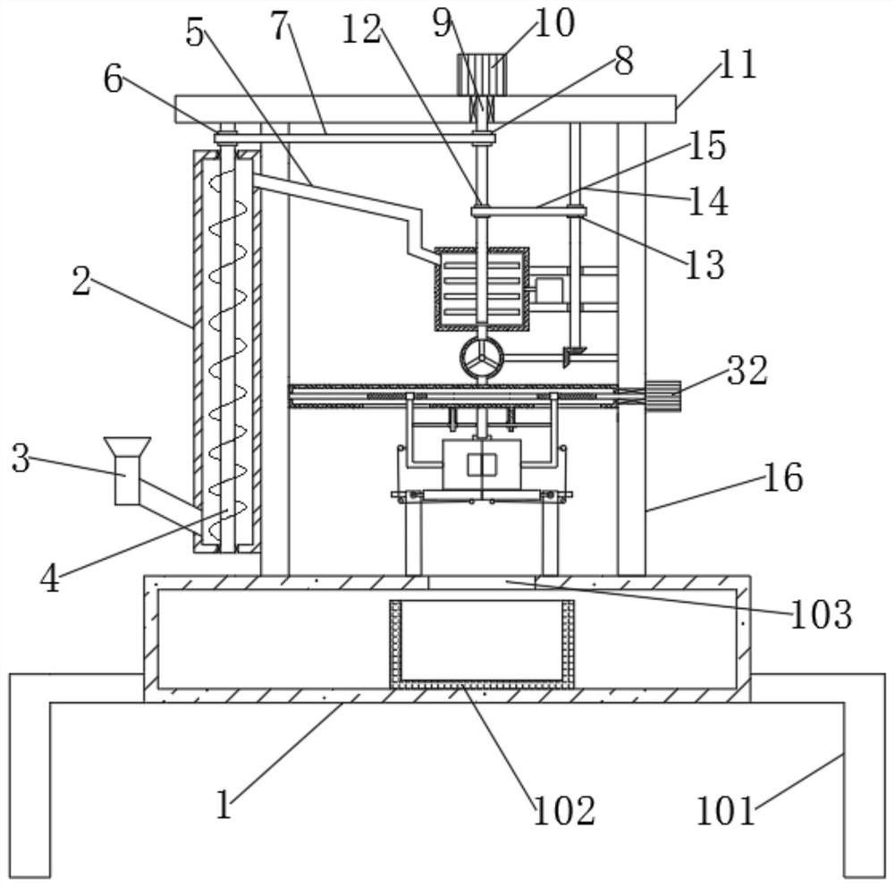
[0041] A mold for forming a water meter shell that is convenient for mold opening and parts extraction, comprising a workbench 1, support legs 101 are installed at the left and right ends of the workbench 1, the front end of the workbench 1 is set as an opening, the upper end is symmetrically installed with brackets 16, and the middle of the upper end is set There is a feeding port 103;

[0042] The upper ends of the two supports 16 are all connected with the bottom end of the top plate 11, the left end of the left support 16 is equipped with a feeding mechanism, and the left end of the right support 16 is connected with the right end of the mixing box 17 through a vertically symmetrical fixed plate 21, between the two supports 16 A box body 33 is installed;

[0043] The top plate 11 upper end is equipped with a first motor 10, the first motor 10 is connected with a rotating shaft-9 downwards, the rotating shaft-9 passes through the top plate 11 downwards, and stretches into t...

Embodiment 2

[0057] The difference from Example 1 is:

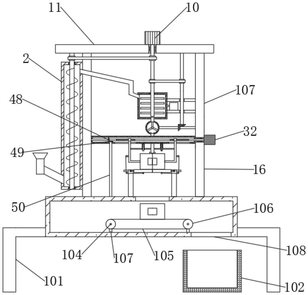
[0058]Inside the workbench 1, a conveying assembly is installed corresponding to the feeding port 103. The conveying assembly includes a No. 5 pulley 106. Two No. 5 pulleys 106 are connected together through a transmission belt 3 105. The two No. 5 pulleys 106 are installed on the shaft 6 104 respectively. Above, two rotating shafts 6 104 are rotatably connected on the mounting bracket 107, and the rear end of one of the rotating shafts 6 104 is equipped with five types of bevel gears 52, the fifth types of bevel gears 52 mesh with the six types of bevel gears 51, and the six types of bevel gears 51 Installed on the rotating shaft seven 50, the rotating shaft seven 50 protrudes upwards from the workbench 1 and extends into the box body 33, and is connected with seven types of bevel gears 49, the seven types of bevel gears 49 mesh with the eight types of bevel gears 48, and the eight types of bevel gears The bevel gear 48 is installed ...


PUM


Abstract

The invention relates to the technical field of water meter shell forming, in particular to a water meter shell forming mold facilitating mold opening and part taking and a forming method of the water meter shell forming mold. The water meter shell forming mold comprises a workbench, and supports are bilaterally symmetrically mounted at the upper end of the workbench; the upper ends of the two supports are connected with the bottom end of a top plate, a feeding mechanism is installed at the left end of the left support, the left end of the right support is connected with the right end of a stirring box through vertically-symmetrical fixing plates, and a box body is installed between the two supports; a heating mechanism is installed on the stirring box, a discharging pipe is installed at the bottom end of the stirring box, the discharging pipe is connected with the upper end of a discharging barrel, and a quantitative discharging mechanism is installed in the discharging barrel; and a mold opening assembly is mounted on the box body and is connected with a buffer mechanism. Through the feeding mechanism, a first motor, the heating mechanism and the quantitative discharging mechanism, fluid raw materials can be conveniently poured into the mold for forming work, and then through cooperation with a second motor, the mold opening assembly, the buffering mechanism and a cooling water tank, a formed water meter shell can be cooled.

Description

technical field [0001] The invention relates to the technical field of forming water meter casings, in particular to a water meter casing forming mold and a forming method that is convenient for mold opening and parts extraction. Background technique [0002] Water meter, foreign name, is an instrument for measuring water flow. Most of them measure the cumulative flow of water. It is generally divided into two types: volumetric water meter and speed water meter. It originated in the United Kingdom. The development of water meters has a history of nearly two hundred years. Choose When determining the specifications of the water meter, you should first estimate the size and flow range of the flow rate that is usually used, and then choose the water meter with the specification that the common flow rate is closest to the value as the first choice. [0003] The caliber of the water meter should be determined according to the caliber of the installation pipe, and the installation...

Claims


Application Information

Patent Timeline
IPC IPC(8): B29C45/46B29C45/18B29C45/66B29C45/72
CPCB29C45/461B29C45/18B29C45/66B29C45/7207
Inventor 仲浩
Owner 连云港苏瑞起重机械有限公司
Why Eureka
Try Eureka