Relay housing comprehensive batch glue scraping equipment for PLC automatic control

A technology of automatic control and relay cover, applied in chemical instruments and methods, cleaning methods and utensils, cleaning methods using tools, etc., can solve the problems of slow processing speed, influence, inconvenient operation, etc., and achieve the effect of improving processing efficiency.

Pending Publication Date: 2021-12-31
蒋件成
View PDF0 Cites 2 Cited by
  • Summary
  • Abstract
  • Description
  • Claims
  • Application Information

AI Technical Summary

Problems solved by technology

[0004] In order to overcome the problem of relay production and assembly process, first install the electrical components on the main frame, dip the pins exposed outside the bottom plate into tin, seal the main frame and the cover with one-component glue, and the sealing hole is also made of one-component Glue seal, put the relay coated with one-component glue into the oven to dry, check the dried relay cover, and scrape off the glue on the cover; the relay cover is provided with four chamfered slopes, At the same time, it is necessary to inspect and scrape the four sides and one top surface, and only one relay cover can be scraped manually when the scraping operation is performed, the processing speed is slow, and the four chamfered slopes It is inconvenient to operate when scraping with an ordinary scraper, and there will be omissions when checking the cover. There are cases where the glue adhering to some covers has not been scraped off, which makes the product have appearance problems after leaving the factory. The shortcoming of bad influence caused by the use experience, the technical problem to be solved by the present invention is: provide a kind of comprehensive batch rubber scraping equipment for PLC automatic control relay cover

Method used


Image

  • Relay housing comprehensive batch glue scraping equipment for PLC automatic control
  • Relay housing comprehensive batch glue scraping equipment for PLC automatic control
  • Relay housing comprehensive batch glue scraping equipment for PLC automatic control

Examples


Embodiment

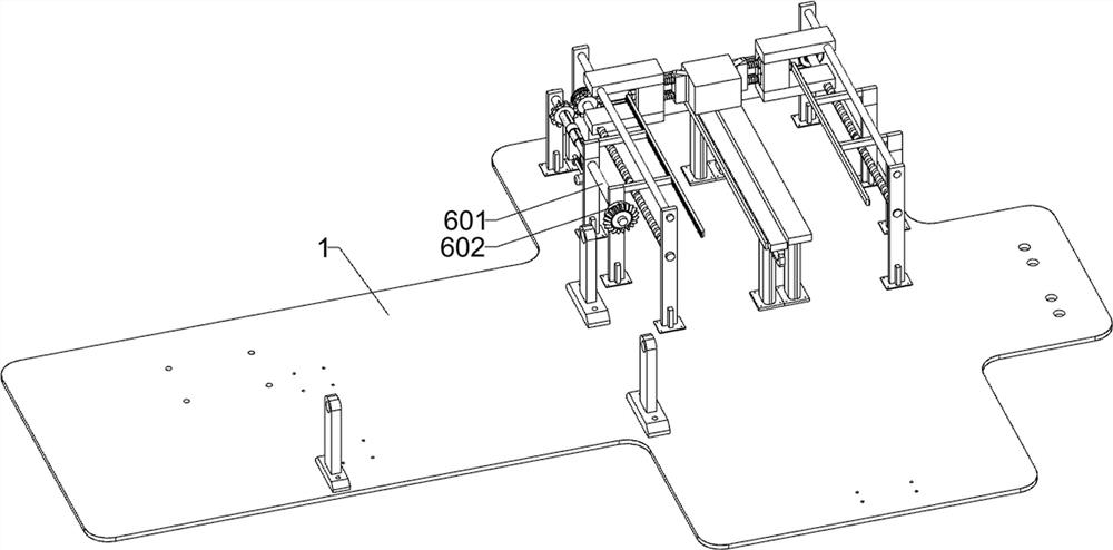
[0036] A comprehensive batch scraping equipment for PLC automation control relay cover, refer to Figure 1-2 As shown, it includes an underframe 1, a first support frame 2, a first fixed frame 3, a first connecting frame 4, a second fixed frame 5, a second support frame 6, a third support frame 7, and a first fixed plate 8. , double-sided squeegee assembly and bonding surface squeegee assembly; the bottom frame 1 is fixedly connected with the first support frame 2, the first fixed frame 3, the first connecting frame 4 and the second fixed frame 5; the first connecting frame 4 It is affixed to the first fixed plate 8; two groups of second support frames 6 and third support frames 7 are all affixed to the bottom frame 1; a double-sided squeegee assembly is arranged above the bottom frame 1; the double-sided squeegee assembly is connected to the The bonding surface scraping assembly is connected; the double-sided scraping assembly is connected with the first supporting frame 2, t...


PUM


Abstract

The invention relates to the field of relay production, in particular to relay housing comprehensive batch glue scraping equipment for PLC automatic control. The technical aim to be achieved by the invention is to provide the relay housing comprehensive batch glue scraping equipment for PLC automatic control. According to the technical scheme, the relay housing comprehensive batch glue scraping equipment for PLC automatic control comprises a first fixing frame, a first connecting frame, a second fixing frame, a second supporting frame, a third supporting frame, a first fixing plate, a double-face glue scraping assembly and a binding face glue scraping assembly; and the double-face glue scraping assembly is connected with the binding face glue scraping assembly. When the equipment is used, glue scraping treatment is carried out on multiple faces of a plurality of relay housings at the same time, inspection is not needed, glue scraping treatment is carried out on the relay housings comprehensively, the problem that products with appearance problems leave factories due to omission of manual treatment is avoided, glue scraping treatment is carried out on a plurality of chamfered slopes at the same time, and the treatment efficiency is greatly improved.

Description

technical field [0001] The invention relates to the field of relay production, in particular to a comprehensive batch scraping equipment for relay covers used in PLC automatic control. Background technique [0002] In the prior art, during the production and assembly process of the relay, the electrical components are first installed on the main frame, the pins exposed outside the bottom plate are dipped in tin, and the main frame and the case are sealed with a single-component glue, and the sealing hole is also made of One-component glue seal, put the relay coated with one-component glue into the oven to dry, check the dried relay cover, and scrape off the glue sticking to the cover; the relay cover is equipped with four inverted Angle bevel, at the same time, it is necessary to inspect and scrape the four sides and one top surface, and only one relay cover can be scraped at a time when the manual scraping operation is performed, the processing speed is slow, and the four i...

Claims


Application Information

Patent Timeline
Patent Type & Authority Applications(China)
IPC IPC(8): B08B1/00B08B13/00
CPCB08B1/005B08B13/00
Inventor 蒋件成
Owner 蒋件成
Why Eureka
Try Eureka