
Optical cable

A technology of optical cable and buffer layer, which is applied in the direction of light guides, optics, optical components, etc., can solve the problems of limited compressive performance and increased specific gravity of optical cables, and achieve the effects of improving compressive performance, avoiding damage to optical fibers, and avoiding direct stress

Pending Publication Date: 2021-12-28
FUTONG GRP JIASHAN COMM TECH CO LTD
View PDF0 Cites 5 Cited by
  • Summary
  • Abstract
  • Description
  • Claims
  • Application Information

AI Technical Summary

Problems solved by technology

[0005] In order to solve the problem that the existing optical cable has limited compressive performance, or the specific gravity of the optical cable will increase significantly when the compressive performance is improved, the present invention provides an optical cable

Method used


Image

  • Optical cable
  • Optical cable
  • Optical cable

Examples


Embodiment

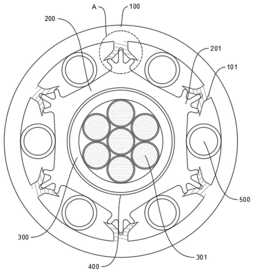
[0040] a kind of like figure 1 The pressure-resistant optical cable shown specifically includes:

[0041] A sheath layer 100, a structural buffer layer 200, a non-woven fabric wrapping layer 400, a bundle tube 300 and an optical fiber layer 301 are sequentially arranged from outside to inside;

[0042] The bundle tube 300 is coated on the outer surface of the optical fiber layer. The optical fiber layer is composed of several optical fiber lines. The optical fiber lines are single-mode optical fibers or multi-mode optical fibers or optical fiber bundles. fixed;

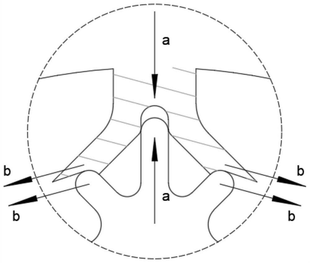
[0043] The radial cross-section of the optical cable of the main body of the structural buffer layer 200 is a regular polygon. For example, in this embodiment, the radial cross-section is a regular hexagon. The edge of the main body of the structural buffer layer 200, namely figure 1 At the corner of the radial cross-section of the main body of the hexagonal structure buffer layer 200, an outwardly protruding inner ...


PUM


Abstract

The invention belongs to the field of communication cables, and particularly relates to an optical cable. The optical cable comprises a sheath layer, a structure buffer layer, a beam tube and an optical fiber layer which are sequentially arranged from outside to inside, the optical cable radial cross section of the structure buffer layer main body is polygonal, the edge part of the structure buffer layer main body is provided with an inner buffer structure protruding outwards, the sheath layer wraps the outer layer of the structure buffer layer, and the inner surface of the sheath layer is provided with an outer buffer structure corresponding to each inner buffer structure; the inner buffer structure comprises at least three edge structures, a middle edge in the center of the inner buffer structure protrudes outwards in the radial direction of the optical cable, side edges are arranged on the two sides of the middle edge, and the inner ends of the side edges and the inner end of the middle edge are connected to the edge portion of the structure buffer layer. The outer buffer structure is provided with an opening, the opening abuts against the side edge, the outer buffer structure is provided with a middle groove in the radial direction of the optical cable, and the outer end of the middle edge of the inner buffer structure extends into the middle groove. The compression resistance of the optical cable can be effectively improved, and meanwhile the problem that the specific gravity of the optical cable is excessively increased is solved.

Description

technical field [0001] The invention belongs to the field of communication cables, in particular to an optical cable. Background technique [0002] Optical cable is a common cable for optical signal transmission in the field of communication. It has developed rapidly in recent years and produced various optical cables. [0003] In the existing optical cables, in order to ensure the axial shaping ability, hanging ability and strength of the optical cables, metal reinforcements are generally arranged in the optical cables. Under normal circumstances, the setting of the strengthening member can indeed effectively improve the performance of the optical cable in all aspects, but in some environments, the setting of the strengthening member will lead to a significant increase in the overall weight / length ratio of the optical cable, that is, the weight of the optical cable per unit length will change. Large, the first and most direct manifestation is that it will lead to increased...

Claims


Application Information

Patent Timeline
Patent Type & Authority Applications(China)
IPC IPC(8): G02B6/44
CPCG02B6/443
Inventor 刘法林喻小明潘泰斌
Owner FUTONG GRP JIASHAN COMM TECH CO LTD
Learn More