Sealing structure of junction box of electromagnetic flowmeter

A technology of electromagnetic flowmeter and sealing structure, which is applied in the application of electromagnetic flowmeter to detect fluid flow, volume/mass flow generated by electromagnetic effects, volume measurement, etc., which can solve unfavorable electromagnetic flowmeter installation and daily maintenance work, and affect electromagnetic flow Problems such as the stability and reliability of meter equipment, the entry of polluting gases, solid particles, and seepage, etc., to achieve the effects of installation positioning and electrical connection, convenience, stability and safety

Active Publication Date: 2021-12-21
开封科隆流量仪表有限公司
View PDF17 Cites 0 Cited by
  • Summary
  • Abstract
  • Description
  • Claims
  • Application Information

AI Technical Summary

Problems solved by technology

[0002] At present, electromagnetic flowmeters are important equipment for fluid flow detection operations, and they are used in a huge amount. However, in actual use, the main control and communication circuit systems of current electromagnetic flowmeter equipment are often installed in junction boxes, and are directly connected to electromagnetic flowmeters through junction boxes. Although the connection of pipelines and other equipment for flowmeter work can meet the needs of use to a certain extent, on the one hand, in use, the junction box of the current electromagnetic flowmeter is relatively difficult to connect and locate between electromagnetic flowmeters, and the operation is cumbersome. , which is not conducive to the installation and daily maintenance of the electromagnetic flowmeter; on the other hand, the sealing protection ability of the current junction box is often relatively poor, and it is often only realized by traditional sealing rings and other equipment, which can easily lead to external polluting gases, Solid particles and seepage enter the junction box, causing the circuit system failure in the junction box, which seriously affects the stability and reliability of the electromagnetic flowmeter equipment.

Method used


Image

  • Sealing structure of junction box of electromagnetic flowmeter
  • Sealing structure of junction box of electromagnetic flowmeter

Examples


Embodiment Construction

[0018] In order to facilitate the implementation of the technical means, creative features, goals and effects achieved by the present invention, the present invention will be further elaborated below in conjunction with specific embodiments.

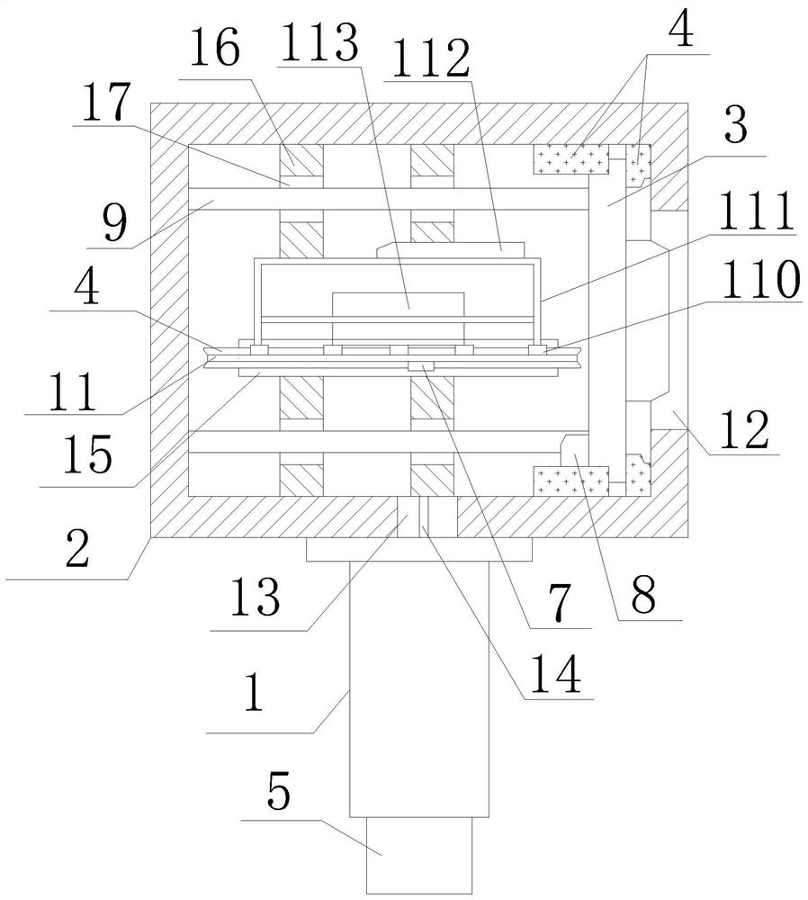
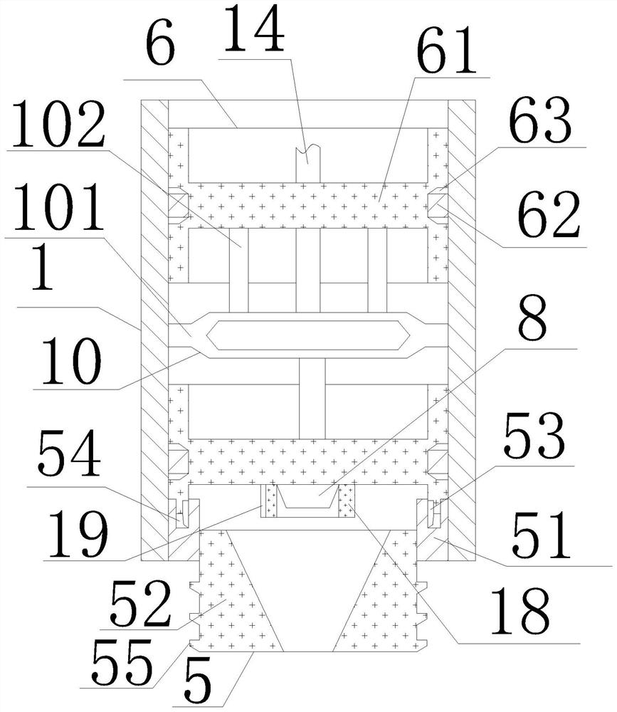
[0019] Such as figure 1 and 2 As shown, a sealing structure of an electromagnetic flowmeter junction box includes a bearing column 1, a bearing box body 2, a control panel 3, a sealing ring 4, a sealing column 5, a sealing plate 6, a main terminal 7, an auxiliary terminal 8, a bearing The spring 9, the positioning spring 10 and the bearing plate 11, wherein the bearing column 1 is a hollow tubular structure with a rectangular axial section, and its upper end surface is connected with the end surface of the bearing box body 2 through a sealed thread, and the axis of the bearing column 1 is connected to the bearing box. The axis of the body 2 is vertically distributed, and the carrying box body 2 is a closed cavity structure with a rectan...


PUM


Abstract

The invention relates to a sealing structure of a junction box of an electromagnetic flowmeter. The sealing structure comprises a bearing column, a bearing box body, a control panel, a sealing ring, a sealing column, sealing plates, a main wiring terminal, an auxiliary wiring terminal and a bearing plate. The upper end face of the bearing column is connected with the wire end face of the bearing box body through sealing threads, and a control opening is formed in the front end face of the bearing box body; the control panel is embedded in the front end face of the bearing box body, the bearing plate is embedded in the bearing box body, the main wiring terminal is connected with the lower end face of the bearing plate and electrically connected with the auxiliary wiring terminal through a wire, and the auxiliary wiring terminal is embedded in the lower end face of the bearing column and connected with the inner side face of the bearing column through the sealing plates. The sealing plates are symmetrically distributed in the upper end face and the lower end face of the bearing column. On one hand, the requirement for matched use of various electromagnetic flowmeters can be effectively met; and on the other hand, an external humid environment and fluid media conveyed by a pipeline can be effectively prevented from invading the junction box.

Description

technical field [0001] The invention relates to a sealing structure of an electromagnetic flowmeter junction box, which belongs to the technical field of flowmeters and sensors. Background technique [0002] At present, electromagnetic flowmeters are important equipment for fluid flow detection operations, and they are used in a huge amount. However, in actual use, the main control and communication circuit systems of current electromagnetic flowmeter equipment are often installed in junction boxes, and are directly connected to electromagnetic flowmeters through junction boxes. Although it can meet the needs of use to a certain extent by connecting the pipelines and other equipment where the flowmeter works, on the one hand, the junction box of the current electromagnetic flowmeter is relatively difficult to connect and locate between the electromagnetic flowmeters during use, and the operation is cumbersome. , which is not conducive to the installation and daily maintenanc...

Claims


Application Information

Patent Timeline
Patent Type & Authority Applications(China)
IPC IPC(8): G01F1/58G01F15/00G01F15/14
CPCG01F1/58G01F15/00G01F15/14
Inventor 姚迎春
Owner 开封科隆流量仪表有限公司
Why Eureka
Try Eureka