
Method for manufacturingflexible stretchable battery pack

A manufacturing method and battery pack technology, which are applied to battery pack components, isolation of batteries from their environment, circuits, etc., can solve the problems of limited bending times, low safety, and inability to stretch and twist, achieving good safety and improving safety. wide range of applications

Pending Publication Date: 2021-12-17
嘉兴极展科技有限公司 +1
View PDF15 Cites 2 Cited by
  • Summary
  • Abstract
  • Description
  • Claims
  • Application Information

AI Technical Summary

Problems solved by technology

[0002] The current flexible battery uses an ultra-thin flexible battery cell, which can be bent and has a certain degree of flexibility. It has the following defects: the number of bending times is limited, and the battery life will be lost if the number of bending times is too high, and the capacity will be reduced at the same time, about 1mAh ~100mAh; moreover, the existing ultra-thin flexible batteries can only be bent, not stretched or twisted
In addition, in order to achieve flexibility and bending, the existing flexible battery products generally have no protective shell, lack of external protection for the flexible battery, the safety is too low, and safety problems such as puncture and rupture are prone to occur

Method used


Image

  • Method for manufacturingflexible stretchable battery pack
  • Method for manufacturingflexible stretchable battery pack
  • Method for manufacturingflexible stretchable battery pack

Examples


Embodiment 1

[0059] An embodiment of the present invention provides a method for manufacturing a flexible and stretchable battery pack, which includes:

[0060] Process 1, the manufacturing steps of the internal cell module, including:

[0061] Place each cell in the mold and inject glue into the cell to form a cell glue injection layer; the cell is packaged in the cell glue injection layer to form an island structure, and one side of the island structure (not covered by the cell glue injection layer) reserved for electrical connection (electrical connection with the PCB board or other cells) adapter plate (circuit expansion interface), the adapter plate through the wire as a bridge and The cells are electrically connected to form an island bridge structure; wherein the cell glue injection layer does not include the side where the cells are located on the adapter plate;

[0062] Place each PCB board in the mold and inject glue into the PCB board to form a PCB board glue injection layer; ...

Embodiment 2

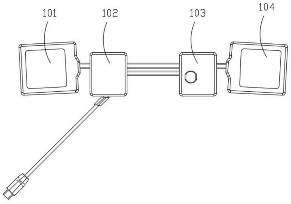
[0072] see Figure 4 , in this embodiment, the internal cell module 100 is a symmetrical structure, which includes a third cell 111, a first PCB board 112, a second PCB board 113, and a fourth cell 114 placed in sequence, and the third cell 111 It is electrically connected to the first PCB board 112, the second PCB board 113 is electrically connected to the fourth electric core 114, the first PCB board 112 and the second PCB board 113 are electrically connected to each other, the first PCB board 112 with the glue injection layer and the The shape and size of the second PCB board 113 of the glue injection layer are basically the same (the size of the first PCB board 112 and the second PCB board 113 in the glue injection layer can be the same or different, and it can be determined by the thickness of the glue injection layer. Appropriately adjusted), so that the internal cell module 100 forms a left-right symmetrical structure centered on the middle.

[0073] See Figure 5-Fig...

Embodiment 3

[0081] In this embodiment, different from Embodiment 1 and Embodiment 2, the internal cell module also includes two electrical connectors (the number of which can be set according to actual needs) electrically connected to each cell and the PCB board. see Figure 16 , the internal cell module 100 includes a fifth cell 131, a third PCB board 132, a fourth PCB board 133, a sixth cell 134, a first electrical connector 135, and a second electrical connector 136 placed in sequence. The five electric cores 131 are electrically connected to the third PCB board 132, the fourth PCB board 133 is electrically connected to the sixth electric core 134, the third PCB board 132 and the fourth PCB board 133 are electrically connected to each other, and the first electrical connector 135 is connected to the sixth electric core 134. The three PCB boards 132 are electrically connected, and the second electrical connector 136 is electrically connected to the fourth PCB board 133 . The shape of t...


PUM

PropertyMeasurementUnit
thicknessaaaaaaaaaa
thicknessaaaaaaaaaa
thicknessaaaaaaaaaa

Abstract

The invention discloses a method for manufacturing a flexible stretchable battery pack. The method comprises the following steps of: manufacturing an internal battery core module: respectively placing each battery core in a mold, injecting a glue into the battery core to form a battery core glue injection layer, placing each PCB in the mold, injecting the glue into the PCB to form a PCB glue injection layer, connecting one or more battery cores with the battery core glue injection layers in series and parallel, and electrically connecting the battery cores with one or more PCBs with the PCB glue injection layers through conducting wires to form an internal battery core module; and manufacturinga stretchable packaging shell: carrying out blow molding, or injection molding, or compression molding or extrusion molding on the internal battery core module by adopting an elastic material to obtain the stretchable packaging shell. According to the manufacturing method disclosed by the invention, each module of the internal battery core module is respectively packaged, and then secondary packaging is carried out through the stretchable packaging shell, so that not only is the good stretchable performance protected, but also the good safety is achieved.

Description

technical field [0001] The invention relates to the technical field of batteries, in particular to a method for manufacturing a flexible and stretchable battery pack. Background technique [0002] The current flexible battery uses an ultra-thin flexible battery cell, which can be bent and has a certain degree of flexibility. It has the following defects: the number of bending times is limited, and the battery life will be lost if the number of bending times is too high, and the capacity will be reduced at the same time, about 1mAh ~100mAh; moreover, the existing ultra-thin flexible batteries can only be bent, but cannot be stretched or twisted. In addition, in order to achieve flexibility and bending, the existing flexible battery products generally have no protective shell, lack of external protection for the flexible battery, the safety is too low, and safety problems such as puncture and rupture are prone to occur. Contents of the invention [0003] A brief overview of...

Claims


Application Information

Patent Timeline
Patent Type & Authority Applications(China)
IPC IPC(8): H01M50/238H01M50/204H01M50/24H01M50/242H01M50/224H01M50/22H01M50/244
CPCH01M50/238H01M50/204H01M50/24H01M50/242H01M50/224H01M50/22H01M50/244Y02E60/10
Inventor 宋泽铭何蕾张留华张浩达肖邹忠刘少鹏闫伟
Owner 嘉兴极展科技有限公司
Learn More