Measuring device and method of leveling rod
A technology of measuring device and leveling rod, which is applied in the field of machinery and can solve the problems of inability to realize the angle measuring function and inconvenient operation.
- Summary
- Abstract
- Description
- Claims
- Application Information
AI Technical Summary
Problems solved by technology
Method used
Image
Examples
Embodiment 1
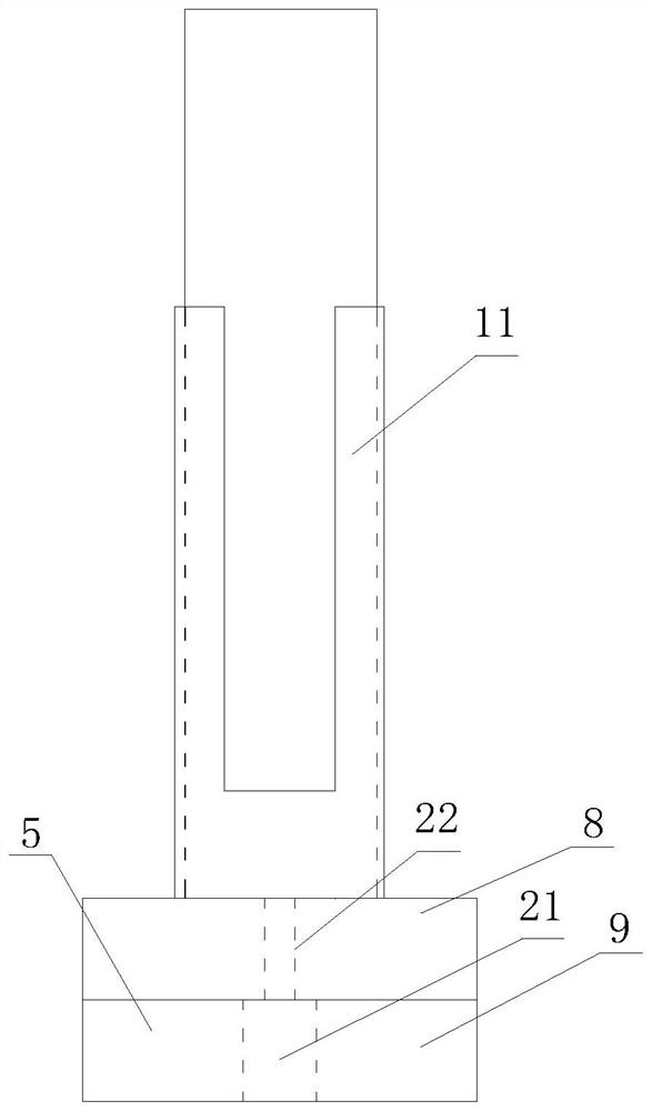
[0042] Such as figure 1 with image 3 As shown, the leveling rod includes a ruler body 1 whose cross-section is elliptical, and also includes a horizontal goniometer, that is, a ruler pad angle measuring turntable, and the horizontal goniometer includes an angle measuring camera horizontal rotation device 5 and Horizontally rotate the angle measuring sensor, the angle measuring camera horizontally rotating device 5 it comprises the first chi pad, the first chi pad comprises the first upper turntable 8 and the first lower chassis 9, the first upper turntable 8 is fixed with a sleeve, said The bottom of the sleeve is raised around, and the four edges around it extend upwards to wrap the four edges of the ruler body, so as not to affect the movement of the telescopic support rod, and the ruler body is fixed in the sleeve. There are a plurality of column holes 12 on the lower part of the ruler body, and a convex column is fixed on the first upper turntable. Cooperate, so that th...
Embodiment 2
[0053] The measuring method of the measuring device of the leveling rod comprises the following steps:
[0054] 1) Select the ruler pad angle measuring turntable for leveling;
[0055] 1A) If you choose leveling, install the ruler pad angle measuring turntable and open the telescopic support rod to support it on the ground. Click the ruler pad angle measuring turntable in the leveling to level the leveling rod through the supporting mobile app. The embedded system controls the rotation of the ruler pad angle measuring turntable, and drives the movement of the telescopic support rod and the universal wheel. The embedded system automatically senses the rotation angle of the leveling camera through the first angle sensor, and adjusts the front and rear sight rulers until the leveling measurement Until the camera can see the ruler body, stop the rotation of the ruler pad angle measuring turntable, so that the ruler body faces each other, then the embedded system reads the data of ...
Embodiment 3
[0063] The difference from Embodiment 1 is that the horizontal goniometer is located on the upper part of the ruler body, close to the vertical goniometer, the ruler body is divided into upper and lower layers, and can be relatively rotatably connected. The fixed plate is symmetrically fixed on the lower layer of the ruler body. There is a motor hole in the center of the lower ruler body for fixing the motor. The motor has a motor shaft. The motor shaft is fixed on the upper layer of the ruler body and can drive the upper part of the ruler body to rotate. Drive the vertical goniometer to rotate horizontally. In addition, for the specific structure of the bottom of the ruler body, please refer to the patent application number: 201921169720.5 Authorization announcement number: 210291281U Invention name: "A level pad", the difference from this patent is that the manual knob is changed to the eighth and ninth motor drive , the transmission gear on the adjustment column meshes with...
PUM
 Abstract
Description
Claims
Application Information
 - R&D Engineer
- R&D Manager
- IP Professional
- Industry Leading Data Capabilities
- Powerful AI technology
- Patent DNA Extraction
Browse by: Latest US Patents, China's latest patents, Technical Efficacy Thesaurus, Application Domain, Technology Topic, Popular Technical Reports.
© 2024 PatSnap. All rights reserved.Legal|Privacy policy|Modern Slavery Act Transparency Statement|Sitemap|About US| Contact US: help@patsnap.com


