
Sliding assembly and air treatment device

A technology of sliding components and sliding parts, applied in the direction of air flow control elements, etc., can solve problems such as high friction

Active Publication Date: 2021-12-17
QINGDAO HAIER AIR CONDITIONER GENERAL CORP LTD +2
View PDF8 Cites 1 Cited by
  • Summary
  • Abstract
  • Description
  • Claims
  • Application Information

AI Technical Summary

Problems solved by technology

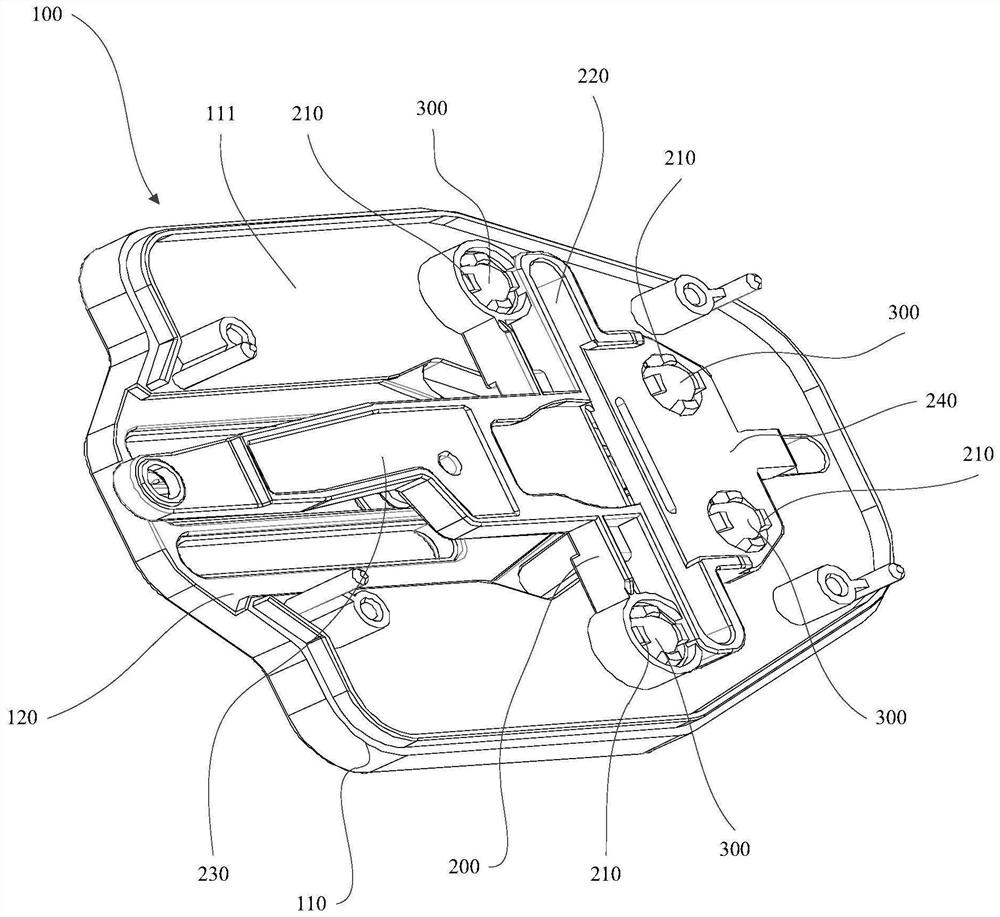
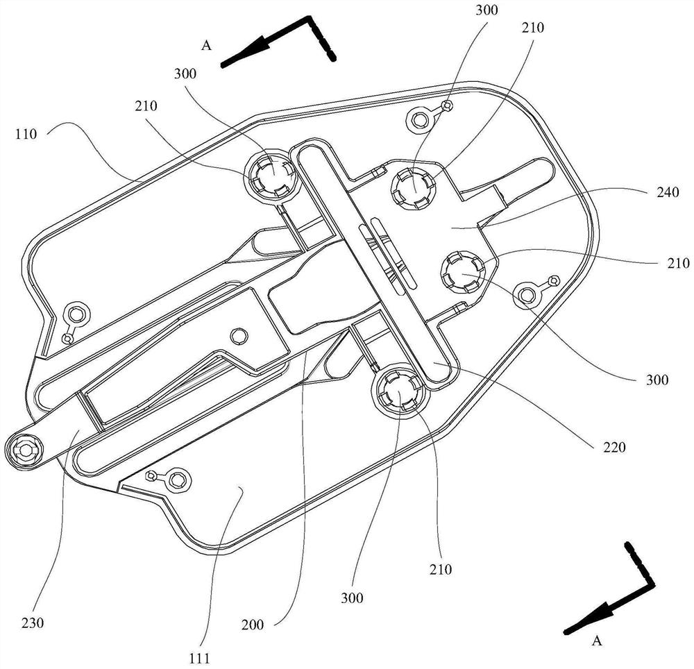
[0005]In order to solve the above problems in the prior art, that is, to solve the problem of large friction when the sliding path of the sliding assembly is a non-linear or non-large arc, this The invention provides a sliding assembly. The sliding assembly includes a base, a sliding piece and a ball. The base is slidably connected to the sliding piece. The base is provided with a first sliding plane, and the sliding piece is provided with a second sliding plane. The first sliding plane and the second sliding plane are set opposite to each other, the second sliding plane is provided with mounting holes corresponding to the balls, the balls are installed in the mounting holes, the balls are in conflict with the first sliding plane and the sliding part, and the balls can roll in the mounting holes , the ball separates the gap space between the second sliding plane and the first sliding plane, and the first sliding plane and the second sliding plane are slidingly matched by the ball

Method used


Image

  • Sliding assembly and air treatment device
  • Sliding assembly and air treatment device
  • Sliding assembly and air treatment device

Examples


Embodiment Construction

[0027] First of all, those skilled in the art should understand that these embodiments are only used to explain the technical principles of the present invention, and are not intended to limit the protection scope of the present invention. Those skilled in the art can make adjustments as needed so as to adapt to specific applications.

[0028] Secondly, it should be noted that, in the description of the present invention, terms such as "inner", "outer" and other indicated directions or positional relationships are based on the directions or positional relationships shown in the drawings, which are only for the convenience of description. It is not intended to indicate or imply that a device or component must have a particular orientation, be constructed or operate in a particular orientation, and thus should not be construed as limiting the invention.

[0029] In addition, it should be noted that, in the description of the present invention, unless otherwise specified and limi...


PUM


Abstract

The invention belongs to the technical field of mechanical cooperation, and particularly relates to a sliding assembly and an air treatment device. The invention aims at solving the problem that the friction force of the sliding assembly with the sliding path being a nonlinear line and a non-large-radian arc line is large. According to the sliding assembly and the air treatment device, the sliding assembly comprises a base, a sliding part and balls, wherein the base is in sliding connection with the sliding part, a first sliding plane on the base and a second sliding plane on the sliding part are oppositely arranged, installing holes corresponding to the balls are formed in the second sliding plane, the balls are installed in the installing holes, the balls abut against the first sliding plane and the sliding part, the balls enable the second sliding plane and the first sliding plane to be spaced to form a clearance space, and the first sliding plane and the second sliding plane are in sliding fit through the balls. The air treatment device comprises the sliding assembly. Through arrangement, the friction force of the sliding assembly of which the sliding path is a non-straight line and a non-large-radian arc line can be reduced, the sliding wear is reduced, and the sliding stability is improved.

Description

technical field [0001] The invention belongs to the technical field of mechanical cooperation, and in particular relates to a sliding assembly and an air treatment device. Background technique [0002] Sliding assembly refers to an assembly with two parts that can slide relative to each other. If the two parts are in the process of relative sliding, if they directly use surface contact, the friction between the two parts is large and easy to wear, and the relative sliding stability of the two parts Poor sex. [0003] In the prior art, in order to reduce the friction between two relatively sliding parts and improve the stability of their relative sliding, it is often used to set a roller shaft on one of the relatively sliding parts so that the two relatively sliding parts pass through The roller shafts are slidingly fitted and slide relative to each other along the rotation direction of the roller shafts. [0004] The existing way of setting the roller shaft can only reduce...

Claims


Application Information

Patent Timeline
IPC IPC(8): F24F13/12
CPCF24F13/12Y02B30/70
Inventor 于兆志徐永伟
Owner QINGDAO HAIER AIR CONDITIONER GENERAL CORP LTD
Learn More