
Lifting power-assisted pedestal pan device

A technology of a toilet device and a toilet cover, which is applied in the field of lift-assisted toilet devices, can solve the problems of odor isolation, inconvenient use of the toilet, and inability to deodorize, etc., and achieves the advantages of convenient use, convenient and timely cleaning, and reduction of peculiar smell Effect

Active Publication Date: 2021-12-17
CRRC SHANDONG CO LTD
View PDF11 Cites 0 Cited by
  • Summary
  • Abstract
  • Description
  • Claims
  • Application Information

AI Technical Summary

Problems solved by technology

[0006] Aiming at the deficiencies in the prior art, the purpose of the present invention is to provide a lift-assist toilet device, in which the toilet cover and sewage discharge of the toilet The valve plate can be interlocked with the lifting process of the toilet chair, and the placement position can be changed at will, which solves the problem that the existing toilet is inconvenient to use and cannot be deodorized and isolated

Method used


Image

  • Lifting power-assisted pedestal pan device
  • Lifting power-assisted pedestal pan device
  • Lifting power-assisted pedestal pan device

Examples


Embodiment 1

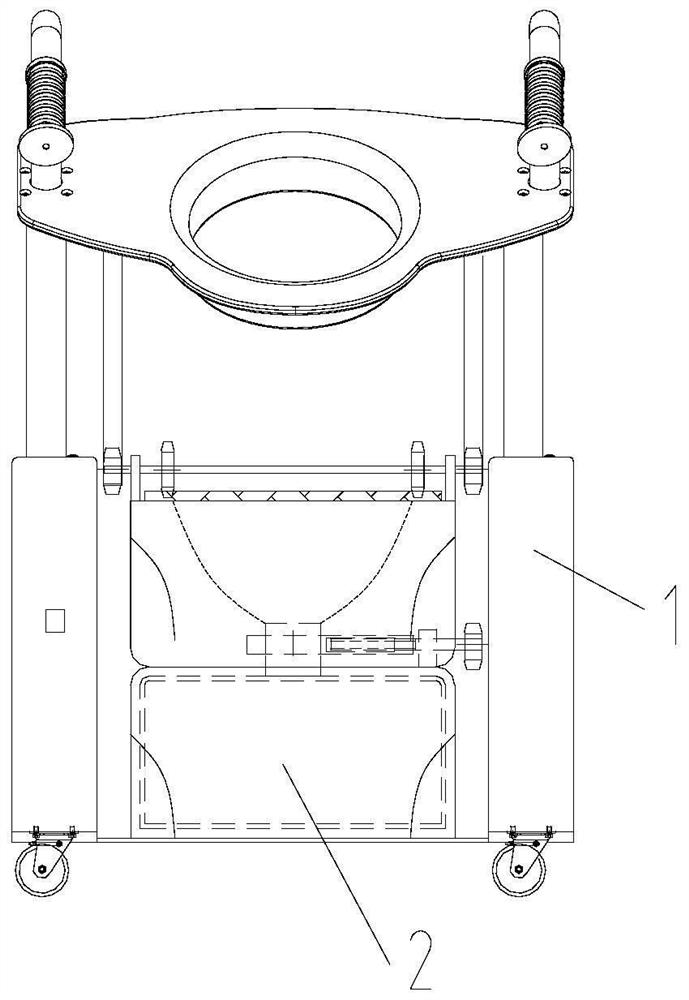
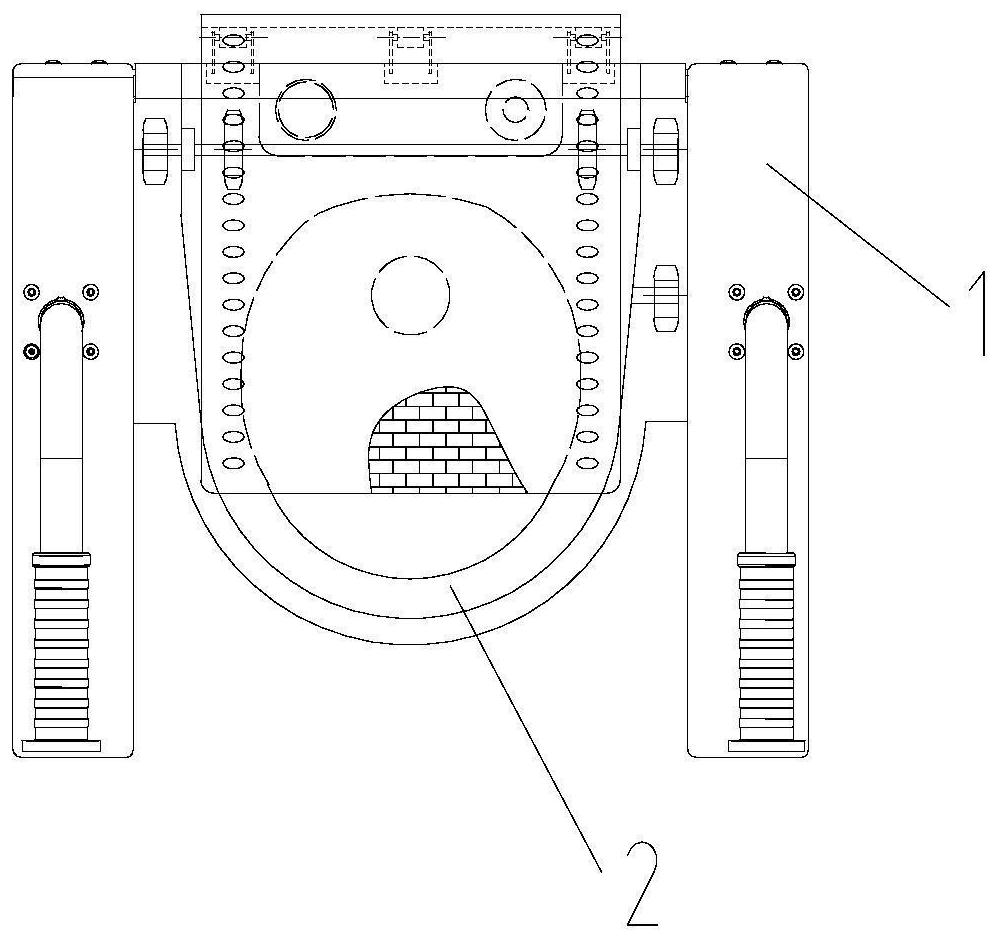
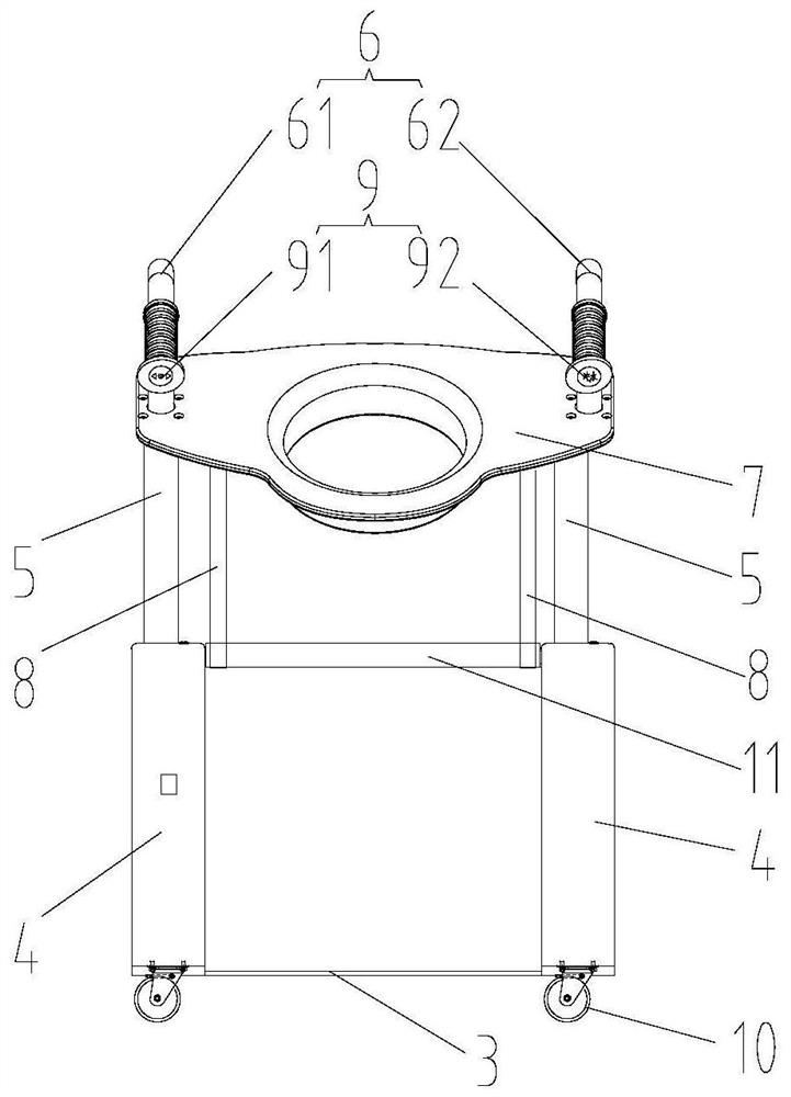
[0042] In a typical embodiment of the present invention, such as Figure 1-Figure 12 As shown, a lifting power-assisted toilet device is proposed, including a toilet chair 1 and a toilet 2, wherein the toilet chair 1 includes two oppositely arranged boxes 4, and the two boxes are respectively arranged on the sides of the toilet chair. Both sides are connected by connecting beam 11.

[0043] Specifically, the connecting beam 11 is arranged at the middle position of the two boxes, respectively connecting the tops of the two boxes, and the middle positions of the bottoms of the two boxes are fixedly connected through the chassis 3, and the bottoms of the two boxes are equipped with walking Roller 10, this walking roller is brakeable, to realize moving at any time and carry out position fixation.

[0044] The two boxes are respectively provided with passages for the lifting rods to move up and down, and the toilet cover 7 is connected between the lifting rods 5, and the two sides...

Embodiment 2

[0066] This embodiment proposes a working method of a lift-assisted toilet device, which adopts the lift-assisted toilet device proposed in Embodiment 1, and the specific working process is as follows:

[0067] When it is necessary to go to the toilet, press the toilet cover lifting control switch to lower the toilet cover;

[0068] During the lowering process of the toilet cover, the second rack and the second gear are meshed and driven to drive the excretion valve plate to move horizontally, so that the round hole of the excretion valve plate and the toilet gradually overlap, and the urinal is connected with the pull-out dirt box; at the same time, the second A gear rack is engaged with the first gear for transmission, and the chain plate pulley is engaged with the groove on the urinal cover for transmission. The urinal cover is gradually opened, and the toilet cover and the urinal are gradually connected.

[0069] When the toilet is over, control the toilet cover lifting co...


PUM


Abstract

The invention discloses a lifting power-assisted pedestal pan device, relates to the field of pedestal pan equipment, solves the problems that an existing pedestal pan is inconvenient to use and cannot deodorize and isolate odor and improves the use comfort, convenience and safety. The lifting power-assisted pedestal pan device comprises a pedestal pan chair, wherein the pedestal pan chair comprises two oppositely arranged box bodies, the box body is provided with a channel for the lifting rods to move up and down, a pedestal pan cover is connected between the lifting rods, and the bottom of the pedestal pan cover is connected with a first gear through a first rack; a pedestal pan is arranged between the two box bodies and located below the pedestal pan cover, a urinal cover is arranged on the top of the pedestal pan, the urinal cover is of a chain plate belt structure, and the urinal cover is connected with the first gear through a transmission mechanism.

Description

technical field [0001] The invention relates to the technical field of toilet equipment, in particular to a lift-assisted toilet device. Background technique [0002] The statements herein merely provide background information related to the present invention and do not necessarily constitute prior art. [0003] The toilet, as a kind of sewage device, its basic principle is to use the gravity of water to convert the potential energy of water into the kinetic energy of water, so as to carry the excrement into the sewer pipe to complete the whole process of sewage discharge. [0004] The inventor found that the elderly, pregnant women and other disabled people have the following pain points or difficulties when using the existing toilet: 1. It is difficult to sit down and get up when going to the toilet; 2. It is inconvenient to go to the toilet because of frequent toilet use; 3. Mobile toilets cannot achieve deodorization and isolation; 4. Some toilets or auxiliary toilet ch...

Claims


Application Information

Patent Timeline
Patent Type & Authority Applications(China)
IPC IPC(8): A47K13/10A47K13/24
CPCA47K13/10A47K13/24Y02A50/30
Inventor 闫续范汪宝珍赵斌冷基鑫李鹏杜正鑫
Owner CRRC SHANDONG CO LTD
Learn More