In-plane sliding micromirror and laser radar

A technology of inner sliding and sliding parts, used in optics, optical components, instruments, etc., can solve the problems of small torsion angle and low micromirror life, achieve low friction, avoid motion failure, and improve the effect of scanning angle

Pending Publication Date: 2021-12-14
RESEARCH INSTITUTE OF TSINGHUA UNIVERSITY IN SHENZHEN +1
View PDF1 Cites 0 Cited by
  • Summary
  • Abstract
  • Description
  • Claims
  • Application Information

AI Technical Summary

Problems solved by technology

[0006] The purpose of the present invention is to provide a kind of in-plane sliding micromirror, to solve the technical problem that the service life of the micromirror in the prior art is relatively low and the torsion angle is small

Method used


Image

  • In-plane sliding micromirror and laser radar
  • In-plane sliding micromirror and laser radar

Examples


Embodiment Construction

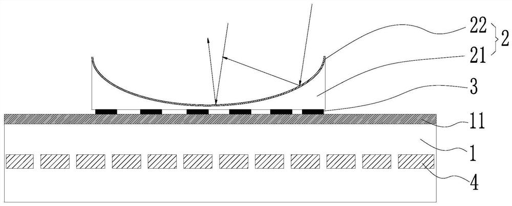
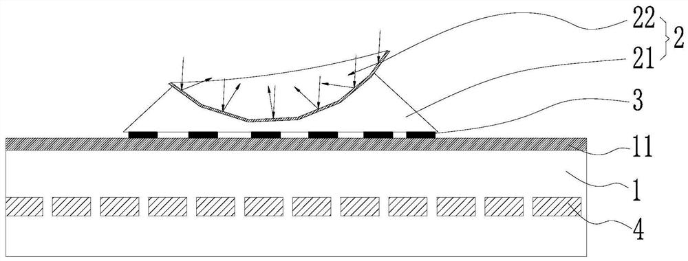
[0027] In order to make the technical problems, technical solutions and beneficial effects to be solved by the present invention clearer, the present invention will be further described in detail below in conjunction with the accompanying drawings and embodiments. It should be understood that the specific embodiments described here are only used to explain the present invention, not to limit the present invention.

[0028] It should be noted that when an element is referred to as being “fixed” or “disposed on” another element, it may be directly on the other element or be indirectly on the other element. When an element is referred to as being "connected to" another element, it can be directly connected to the other element or indirectly connected to the other element.

[0029] It is to be understood that the terms "length", "width", "top", "bottom", "front", "rear", "left", "right", "vertical", "horizontal", "top" , "bottom", "inner", "outer" and other indicated orientations...


PUM


Abstract

The invention provides an in-plane sliding micromirror and a laser radar, the in-plane sliding micromirror comprises a substrate, a mirror surface part arranged on the substrate, a sliding part arranged between the substrate and the mirror surface part, and a driving part used for driving the sliding part to move, the mirror surface part comprises a reflecting surface, the reflecting surface has at least two reflecting angles and the sliding part drives the mirror surface part to slide on the substrate and switch the reflection angle. The mirror surface part can be driven by the sliding part to slide, the mirror surface part can be switched to different reflection angles during sliding, a traditional mode that a torsion arm drives the scanning mirror to rotate is changed into an in-plane sliding mode, the scanning angle of the micro-mirror to a light beam can be greatly increased, long-time stable scanning is achieved, and the in-plane sliding micromirror has long service life.

Description

technical field [0001] The invention belongs to the technical field of laser radar, and more specifically relates to an in-plane sliding micromirror and laser radar. Background technique [0002] Lidar is a device that scans the surrounding space and obtains spatial parameters by emitting laser signals. It is widely used in geographic mapping, environmental detection, industrial scanning or unmanned driving and other industries. At present, the beam scanning method of lidar is mainly motor scanning, but the scanning motor has obvious defects such as large size, high power consumption, complex control circuit and algorithm, which limits the development of miniaturization, integration and low power consumption of lidar The speed of development in other directions also restricts the further popularization and application of lidar. [0003] Micro-electromechanical system (Micro, Electro Mechanical System, hereinafter referred to as MEMS) micromirror is based on mature semicondu...

Claims


Application Information

Patent Timeline
Patent Type & Authority Applications(China)
IPC IPC(8): G01S7/481G02B26/08G02B26/10
CPCG01S7/4817G02B26/0833G02B26/101
Inventor 彭德利郑泉水
Owner RESEARCH INSTITUTE OF TSINGHUA UNIVERSITY IN SHENZHEN
Why Eureka
Try Eureka