Automatic discharging frame

A technology of automatic feeding and main frame, which is applied in thin material processing, coiling, transportation and packaging, etc. It can solve the problems of less tension, failure to use normally, labor occupation and other problems, and achieve uniform tension , save manpower, eliminate the effect of manual feeding operation

Pending Publication Date: 2021-12-14
JINAN YI CHAU LASER TECH CO LTD
View PDF7 Cites 0 Cited by
  • Summary
  • Abstract
  • Description
  • Claims
  • Application Information

AI Technical Summary

Problems solved by technology

[0003] The purpose of the present invention is to solve the problem that some materials rely on tensile force due to their own characteristics, which will lead to tensile deformation, and cannot be used normally after deformation. Common feeding method...

Method used


Image

  • Automatic discharging frame
  • Automatic discharging frame
  • Automatic discharging frame

Examples


Embodiment 1

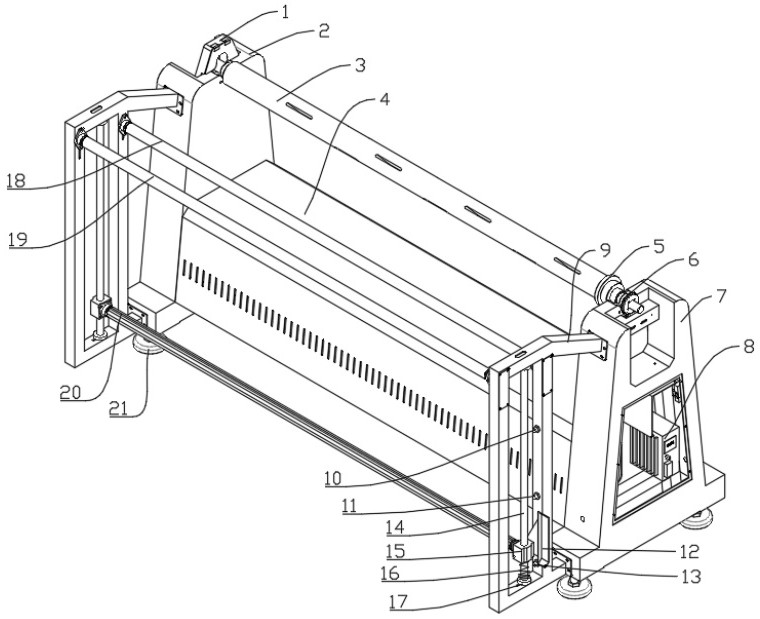
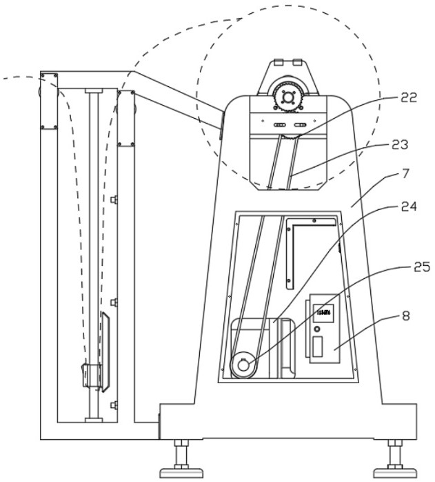
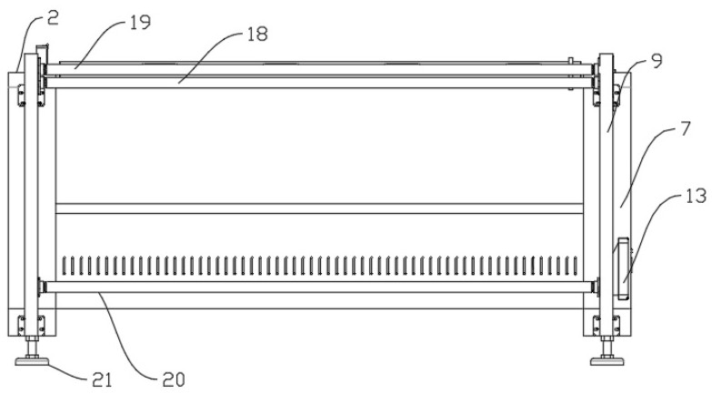
[0025] refer to Figure 1-3 , a kind of automatic unwinding frame, comprises main frame left support 2 and main frame 4, main frame left support 2 and main frame 4 are fixedly connected by welding, main frame 4 right side is welded with main frame right support 7, main frame The bottoms of the left support 2 and the right support 7 of the main frame are respectively connected by bolts with two adjustment feet 21, and the two adjustment feet 21 on the left and right sides are symmetrically distributed, and a control computer 8 is arranged inside the lower side of the right support 7 of the main frame;

[0026] A protective cover 1 is fixedly connected to the left support 2 of the main frame, and an inflatable shaft 3 is placed in the protective cover 1 and the left support 2 of the main frame. The right side is provided with a driven gear 6, and the driven gear 6 is fixedly sleeved on the right end of the inflatable shaft 3, and the right support 7 of the main frame is connecte...

Embodiment 2

[0035] refer to Figure 1-3 , an automatic unwinding rack. In the specific implementation process, the flower-shaped toothed roller is used as the material tensioning shaft 20, which can have a leveling effect on the material when rolling, and the middle wrinkle phenomenon of the material can be rolled under the bevel tooth surface. , to level the material, which plays an important role in the later processing and precision;

[0036]The invention reduces the tensile force on the material when the material is sorted, ensures that the material is always in a state of flatness and less tension when unloading, eliminates the manual unloading operation, and saves a lot of manpower.


PUM


Abstract

The invention discloses an automatic discharging frame, and belongs to the technical field of electric discharging. The automatic discharging frame comprises a main frame, a main frame left support is fixed to the left side of the main frame, and a protective cover is fixedly connected to the main frame left support. An air expansion shaft is arranged on the main frame left support, a material positioning ring sleeves the right side of the air expansion shaft, and a driven gear is arranged on the right side of the material positioning ring and fixedly sleeves the right end of the air expansion shaft. A main frame right support is fixedly connected to the right side of the main frame, a control computer is arranged on the lower side of the interior of the main frame right support, a right flattening square cloth support is arranged on the front side of the main frame right support, and a first-stage flattening shaft is arranged at the front end of the left right side of the right flattening square cloth support. Pulling force borne by materials is reduced, it is guaranteed that the materials are always in a flat and low-tension state in the discharging process, manual discharging operation is completely eradicated, a large amount of manpower is saved, and an important effect is achieved on later processing and precision.

Description

technical field [0001] The invention relates to the technical field of electric discharging, in particular to an automatic discharging rack. Background technique [0002] In the pre-arranging process before product processing, it is necessary to pre-arrange the materials to be processed to ensure that when the materials are placed, the materials will not be damaged due to the problem of placement and accumulation, which will affect the product processing and reduce the product quality. At this time, it is necessary Store the material on the rack; When the ordinary unloading rack is working, one side is placed with materials fixed, and the other side simply relies on the pulling force that cannot be adjusted to drag the materials to pull out the materials to be sorted, adjust them, and obtain the sorted materials; However, due to its own characteristics, some materials rely on tension, which will lead to deformation under tension, and cannot be used normally after deformat...

Claims


Application Information

Patent Timeline
IPC IPC(8): B65H16/10B65H23/185B65H26/02B65H23/00B65H23/34B65H27/00
CPCB65H16/103B65H23/185B65H26/02B65H23/00B65H23/34B65H27/00B65H2701/19
Inventor 殷良马海江赖美玲朱西维
Owner JINAN YI CHAU LASER TECH CO LTD
Why Eureka
Try Eureka