Forming method of deep-cavity thin-wall metal component with extremely small fillet radius

A technology of fillet radius and metal components, which is applied in the field of forming thin-walled metal components with extremely small fillet radii and deep cavities, can solve the problems of uneven stress on the blank, insufficient accuracy of local fillet dimensions, and failure to form, etc., to achieve Reduce the uneven and unreasonable material flow, solve the uneven and unreasonable wall thickness distribution, and reduce the effect of mold processing accuracy

Inactive Publication Date: 2021-12-10
DALIAN UNIV OF TECH
View PDF6 Cites 1 Cited by
  • Summary
  • Abstract
  • Description
  • Claims
  • Application Information

AI Technical Summary

Problems solved by technology

[0005] The purpose of the present invention is to provide a new forming manufacturing method to solve the problems caused by the irregular geometry of the rigid mold and the blank, the blank being affected The force condition is not uniform, resulting in uneven deformation of each area on the original blank, and then there are problems such as uneven wall thickness distribution, local wrinkles, poor mold fit, and insufficient accuracy of local fillet dimensions, and the existing expansion-compression composite forming process High requirements for liquid chamber pressure regulation, high pressure source, high pressure sealing, etc., need to use high-end servo presses, and problems such as the inability to simultaneously form the bottom and small fillets around the bottom, etc., resulting in the formation of deep cavity thin-walled metal components with extremely small fillet radii Extremely inefficient or unshapeable issues

Method used


Image

  • Forming method of deep-cavity thin-wall metal component with extremely small fillet radius
  • Forming method of deep-cavity thin-wall metal component with extremely small fillet radius
  • Forming method of deep-cavity thin-wall metal component with extremely small fillet radius

Examples


Embodiment 1

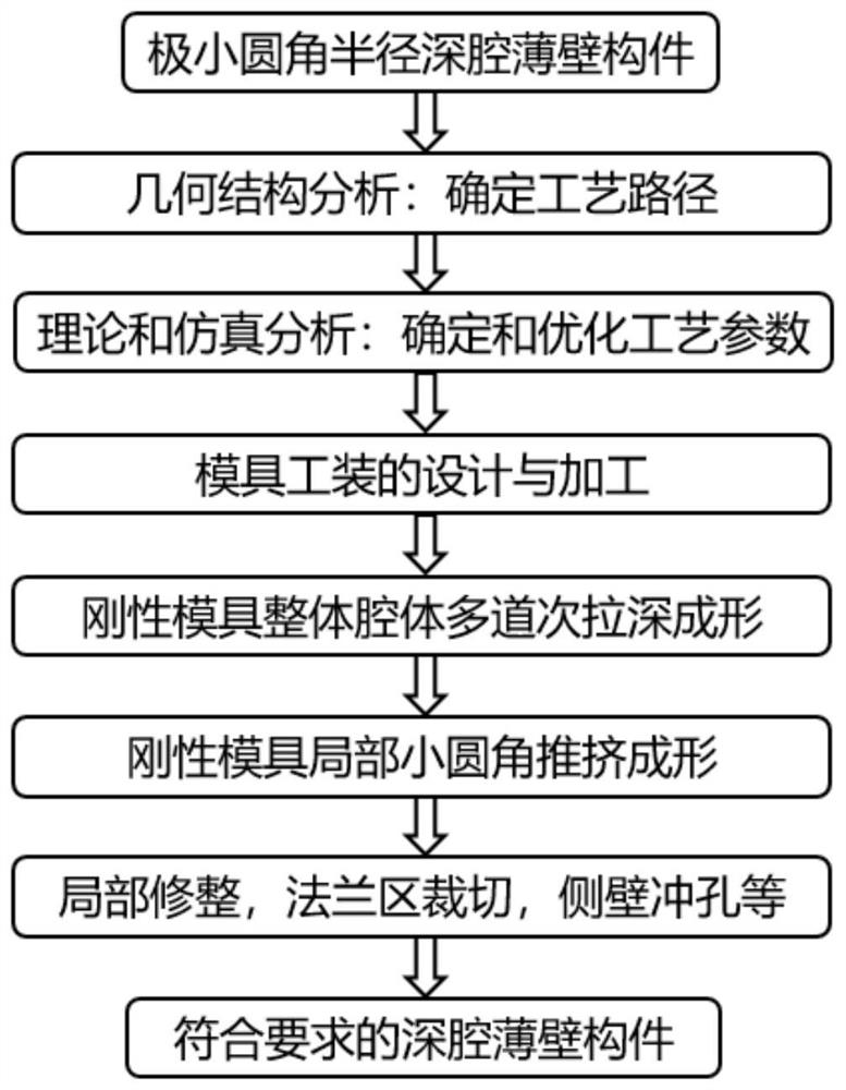
[0030] Example 1: Combining figure 1 , figure 2 , image 3 , Figure 4, Figure 5, Image 6 Illustrate the forming method of extremely small fillet radius deep cavity thin-walled metal member of the present invention, this method is to carry out according to the following steps:

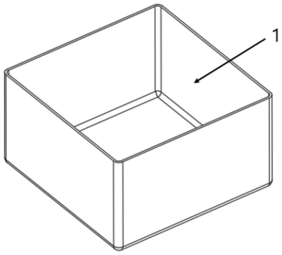
[0031] Step 1. Geometric analysis and process route determination of thin-walled components: if Image 6 As shown, it is the part given in the example. The cavity depth of the part is 100mm, the wall thickness is 2.5mm, and the fillet radius of the transition small fillet is 5mm, which is a typical deep cavity thin-walled metal component with a very small fillet radius. The diameter-thickness ratio of the small fillet of this component is 2, and it is difficult to form it only by deep drawing. It is determined that the forming process of the overall cavity is rigid mold multi-pass deep drawing, and the forming process of local small fillet is rigid mold push forming. .

[0032] Step 2. Formulatio...

Embodiment 2

[0038] Embodiment 2: In conjunction with Fig. 5, in step 1 to step 5, geometric analysis can be carried out for different materials or different parts with different cross-sectional shapes, grasping the factor that the circumference of the cross-section remains unchanged before and after pushing, that is, in During the pushing process, only the shape changes but no compression occurs, and the straight wall section does not change. The deformation is mainly concentrated in the rounded corner area. According to the cross-sectional shape of the specific component, establish a theoretical model to coordinate the relationship between the amount of pushing and the size of the drawing fillet. If it is difficult to achieve a small fillet in drawing forming, the size of the drawing forming fillet can be enlarged to reduce the difficulty of drawing forming , increasing the amount of pushing can also meet the size requirements; if pushing forming is difficult to achieve, you can reduce th...

Embodiment 3

[0040] Embodiment 3: In conjunction with Fig. 4, in step 1 to step 5, the pushing sequence of the side and bottom fillets should be considered when pushing the small fillet, and the process parameters, mold design and tooling should be determined according to the determined pushing sequence. It is preferred to push in all directions at the same time. At this time, the deformation of the fillet and the junction of the fillet can be more coordinated. It can also be pushed separately, pushing in both horizontal directions and pushing at the bottom. At this time, the coordinated deformation of the junction area can be controlled by different pushing amounts, so that the pushing of small round corners can be carried out smoothly, and parts that meet the dimensional accuracy requirements can be obtained. Other steps are with embodiment 1.

[0041] The beneficial effect of this embodiment is that the pushing sequence is reasonably selected according to different forming difficulties,...


PUM

PropertyMeasurementUnit
depthaaaaaaaaaa

Abstract

The invention belongs to the field of forming and manufacturing of deep-cavity thin-wall metal components, and provides a forming method of a deep-cavity thin-wall metal component with an extremely small fillet radius. According to the forming method of the deep-cavity thin-wall metal component with the extremely-small fillet radius, the integral cavity is formed through drawing of the rigid die, the extremely-small fillet is formed through pushing of the small fillet of the rigid die, the drawing forming process and the extremely-small fillet forming process are independent from each other, the problems of wrinkling, cracking and the like in the simultaneous forming process of the drawing forming process and the extremely-small fillet forming process are avoided, and the problem that the extremely-small fillet is difficult to form or even cannot be formed can be solved. According to the forming method of the deep-cavity thin-wall metal component with the extremely-small fillet radius, the method of integral cavity deep-drawing forming and local small fillet pushing forming is high in pertinence and operability, the requirement for the fillet size of all the deep-drawing forming positions is lowered, the deep-drawing forming pass can be greatly reduced, and the formability and the forming efficiency of the deep-cavity thin-wall metal component with the extremely-small fillet radius can be effectively improved.

Description

technical field [0001] The invention belongs to the field of forming and manufacturing deep-cavity thin-walled metal components, in particular to a forming method for deep-cavity thin-walled metal components with extremely small fillet radius. Background technique [0002] Thin-walled metal components are a very important type of components in the fields of aviation, aerospace, automobiles, high-speed rail, etc. They usually bear complex forces and thermal loads, and put forward high requirements for their dimensional accuracy and dimensional stability. At the same time, in order to achieve reasonable and reliable assembly with other adjacent components, thin-walled metal components are generally designed to have a structural form with deep cavities, special-shaped cross-sections, and local small rounded corners. As high-end equipment such as aerospace and automobiles have higher and higher requirements for structural lightweight, high reliability, and long life, the structu...

Claims


Application Information

Patent Timeline
Patent Type & Authority Applications(China)
IPC IPC(8): B21D35/00
CPCB21D35/001B21D35/002B21D22/20G06F30/20B21D51/52G06F30/17G06F2113/24G06F2119/18
Inventor 袁杭何祝斌苑世剑
Owner DALIAN UNIV OF TECH
Why Eureka
Try Eureka