Centrifugal fan and range hood

A centrifugal fan and air duct technology, applied in the direction of oil fume removal, machines/engines, mechanical equipment, etc., can solve the problems of not making full use of the eddy current area, failing to realize the air volume, and delaying the separation of the boundary layer, so as to eliminate the eddy current effect and improve Ventilation efficiency and the effect of increasing ventilation volume

Pending Publication Date: 2021-12-07
QINGDAO HAIER WISDOM KITCHEN APPLIANCE CO LTD +1
View PDF1 Cites 0 Cited by
  • Summary
  • Abstract
  • Description
  • Claims
  • Application Information

AI Technical Summary

Problems solved by technology

[0004] In the above solution, a flow guiding structure is arranged on the back of each fan blade, and the flow guiding structure is installed on the surface of the fan blade to change the parameters of the boundary layer of the blade, delay the separation of the boundary layer, and prevent the air flow at the trailing edge of the fan blade. Vortex shedding occurs at the vortex area. Although this solution does not affect the fan air volume when solving the eddy current problem, it does not make full use of the eddy current area and cannot achieve the effect of increasing the air volume.

Method used


Image

  • Centrifugal fan and range hood
  • Centrifugal fan and range hood
  • Centrifugal fan and range hood

Examples


Embodiment Construction

[0052]In order to make the purpose, technical solutions and advantages of the embodiments of the present invention more clear, the technical solutions in the embodiments will be clearly and completely described below in conjunction with the drawings in the embodiments of the present invention. The following embodiments are used to illustrate the present invention , but not to limit the scope of the present invention.

[0053] In the description of the present invention, it should be noted that the orientation or positional relationship indicated by the terms "upper", "inner" and "outer" are based on the orientation or positional relationship shown in the drawings, and are only for the convenience of describing the present invention and simplified descriptions, rather than indicating or implying that the device or element referred to must have a specific orientation, be constructed and operate in a specific orientation, and thus should not be construed as limiting the invention....


PUM


Abstract

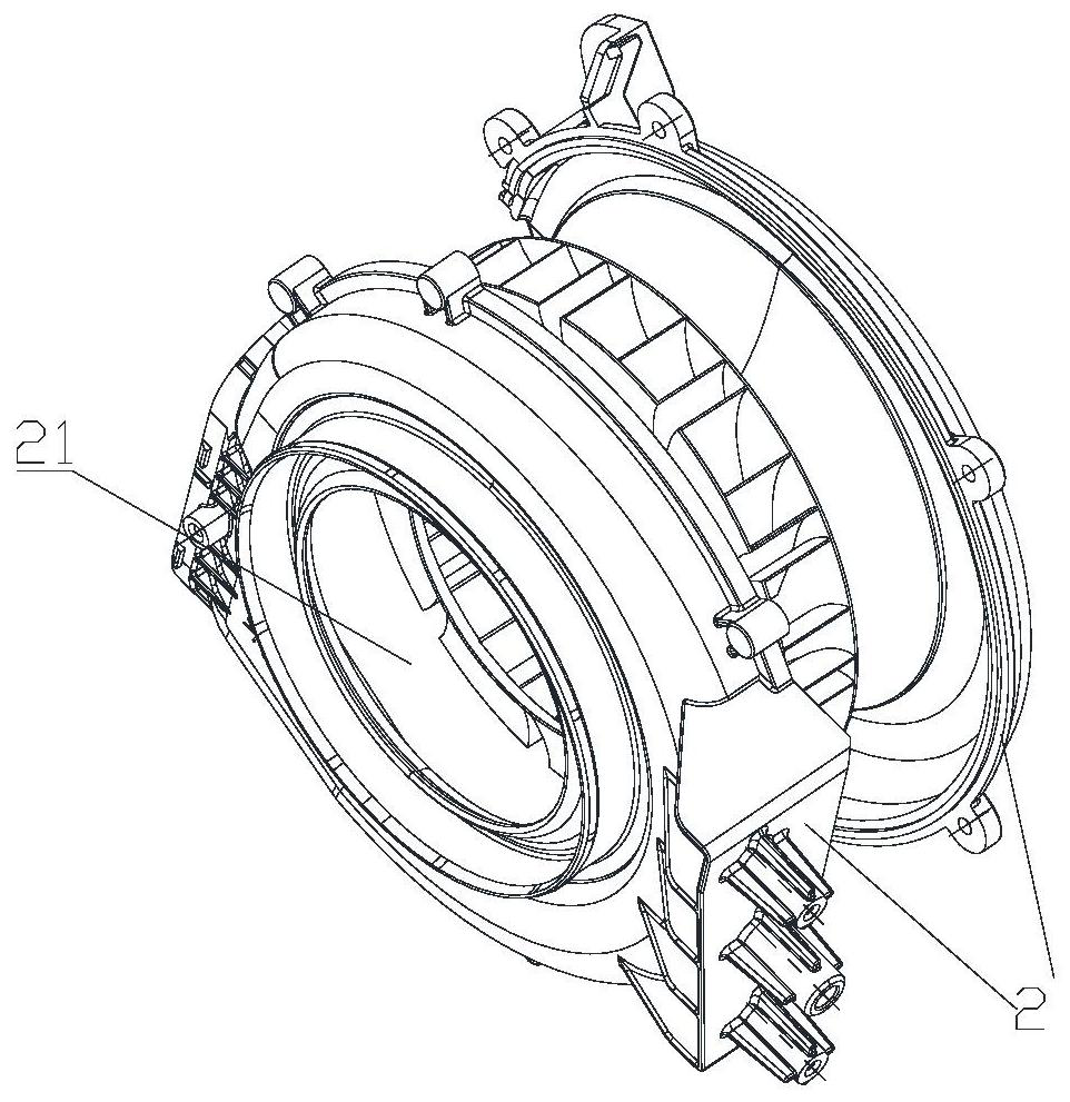
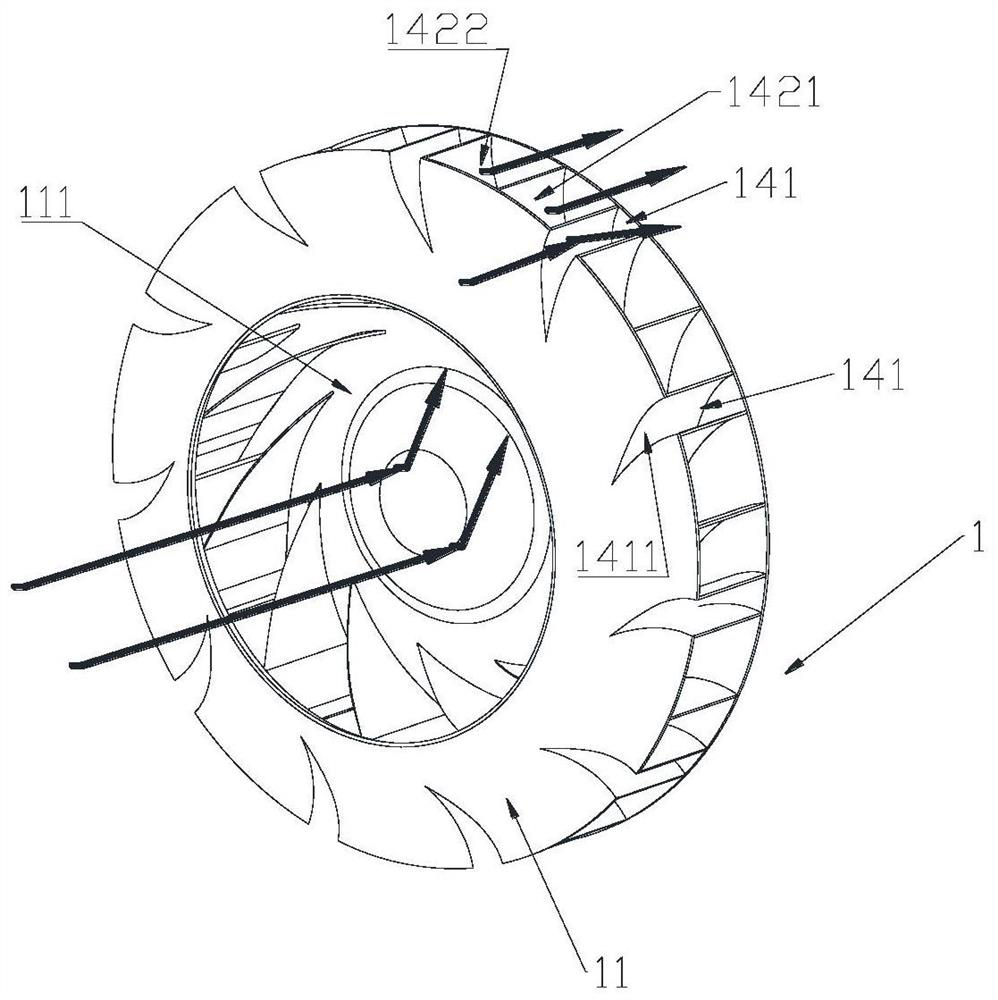
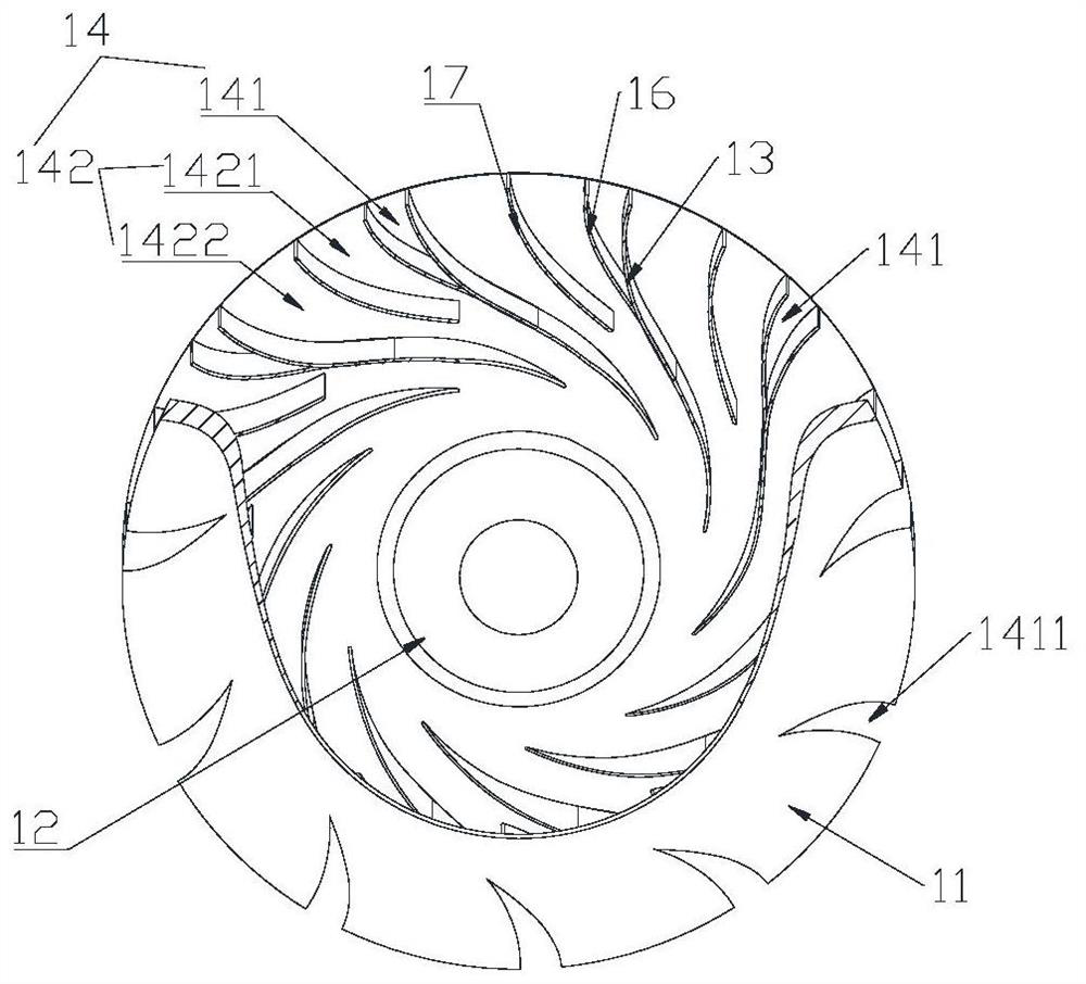
The invention discloses a centrifugal fan and a range hood. The centrifugal fan comprises an impeller and a plurality of main fan blades; the impeller comprises a front disc, a main air inlet and a bottom disc; the main air inlet is formed in the center of the front disc and used for feeding air into the impeller; the bottom disc is arranged opposite to the front disc; the main fan blades extend from the center of the impeller to the periphery and are sequentially distributed between the front disc and the bottom disc in the circumferential direction, an air outlet channel is formed between every two adjacent main fan blades, and the air outlet channels are matched with the main air inlet to form a main air channel; and at least one air outlet channel is internally provided with an auxiliary air channel, the front disc is correspondingly provided with an auxiliary air inlet used for feeding air into the auxiliary air channel, and the auxiliary air inlet is formed in the position close to the periphery of the front disc relative to the main air inlet. According to the centrifugal fan, ventilation can be achieved through the main air channels of the impeller and can also be achieved through the auxiliary air channels, and the ventilation quantity is increased; and in addition, the auxiliary air channels are arranged in the corresponding air outlet channels, so that the pressure difference in the air outlet channels can be reduced, the vortex effect is reduced, and then noise is reduced.

Description

technical field [0001] The invention belongs to the field of household appliances, and in particular relates to a centrifugal fan and a range hood. Background technique [0002] In the existing centrifugal fans, the wind enters between the two blades through the same air inlet on the front plate to form an air duct, and the air volume is limited; in addition, when the centrifugal fan is running, the impeller rotates at a high speed, and the airflow between the blades of the impeller is in the air. Driven by the blade, it rotates with the impeller. Under the action of centrifugal force, the airflow between the blades is thrown to the free end of the blade, and the boundary layer airflow on the leeward surface of the blade is stripped when it is close to the free end of the blade. Due to the phenomenon of separation from the leeward side of the fan blade, the air flow separated from the leeward side forms a vortex near the free end of the fan blade. This vortex not only reduce...

Claims


Application Information

Patent Timeline
Patent Type & Authority Applications(China)
IPC IPC(8): F04D29/28F04D29/30F04D29/66F24C15/20
CPCF04D29/281F04D29/30F04D29/663F24C15/20
Inventor 宋明真郑健宋颜金李涛
Owner QINGDAO HAIER WISDOM KITCHEN APPLIANCE CO LTD
Why Eureka
Try Eureka