Large efficient remote control compressor for oil exploitation

A remote control, compressor technology, applied in pump control, production of fluids, mechanical equipment, etc., can solve the problems of inconvenient maintenance, unfavorable compressor stay and fixed, complicated compressor installation, etc., to achieve the effect of ensuring stability and simple operation.

Inactive Publication Date: 2021-12-07
江西三犇气体科技有限公司
View PDF0 Cites 0 Cited by
  • Summary
  • Abstract
  • Description
  • Claims
  • Application Information

AI Technical Summary

Problems solved by technology

[0004] First, there is no fixed mechanism when the compressor inlet pipe and outlet pipe are connected to the external connecting pipe, so that under high-depth operations, once loose and deflated, maintenance is very inconvenient
[0005] Second, the existing compressors are generally installed inside the larger drill collar, but because the inner wall of the drill collar has a circular structure, it is unfavorable for the compressor to stay fixed inside the drill collar, which makes the installation of the compressor very difficult. cumbersome

Method used


Image

  • Large efficient remote control compressor for oil exploitation
  • Large efficient remote control compressor for oil exploitation
  • Large efficient remote control compressor for oil exploitation

Examples


Embodiment 1

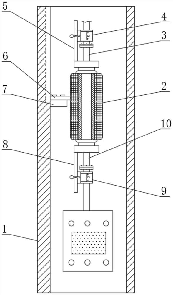
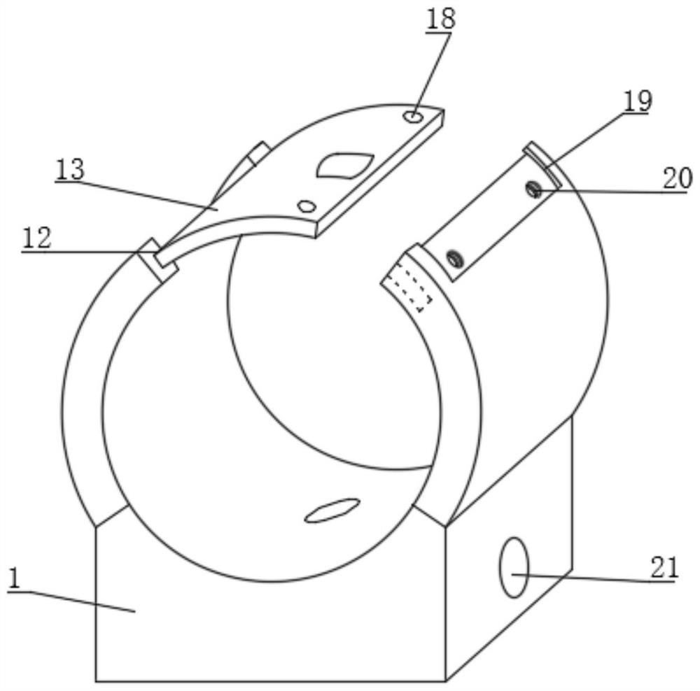
[0041] Embodiment one, with reference to Figure 1-4, a large-scale high-efficiency remote-controlled compressor for oil development, including a drill collar 1, characterized in that a compressor 2 is installed inside the drill collar 1, and an air inlet pipe 3 is arranged at one end of the compressor 2, and the air inlet pipe 3, a first support plate 5 is arranged below, and a first fixing mechanism 4 is installed on the top surface of the first support plate 5, and an exhaust pipe 10 is arranged at the other end of the compressor 2, and an exhaust pipe 10 is arranged under the exhaust pipe 10. The second support plate 8, the top surface of the second support plate 8 is provided with a second fixing mechanism 9, and the inside of the first fixing mechanism 4 and the second fixing mechanism 9 is provided with a first arc-shaped fixing plate 11 and a second arc-shaped fixing plate 11. shaped fixing plate 27, the top surface of the first arc-shaped fixing plate 11 is provided w...

Embodiment 2

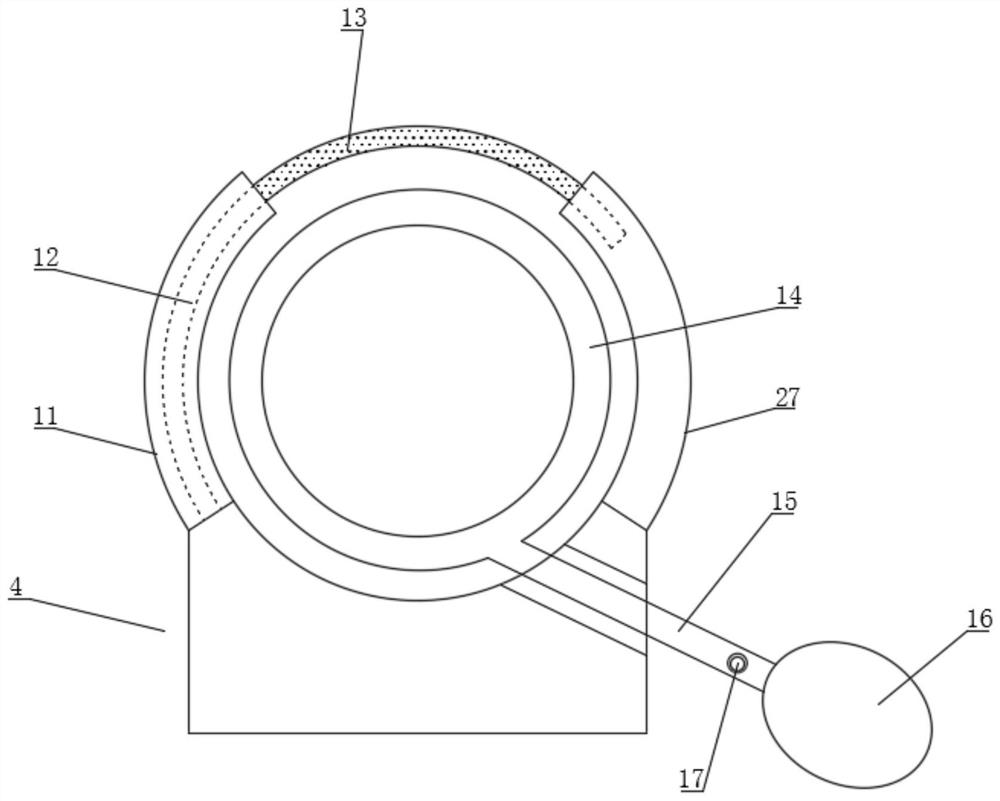
[0042] Embodiment two, refer to figure 1 , 2 and Figure 5 , the inside of the first fixing mechanism 4 and the second fixing mechanism 9 is provided with an extruding mechanism 14, and the inside of the extruding mechanism 14 is provided with an air bag, and one end of the air bag is connected with a pipe 15, and one end of the pipe 15 is provided with a pressing Ball 16, the surface of the pipeline 15 is provided with an air release valve 17, the airbag is a hollow cylindrical structure, the outer wall surface of the airbag is provided with a second extrusion protrusion 23, and the inner wall surface of the airbag is provided with a first extrusion convex grain 22, the first extrusion convex grain 22 and the second extrusion convex grain 23 are equidistantly arranged on the inner wall surface and the outer wall surface of the airbag, by setting the extrusion mechanism 14, the extrusion mechanism 14 is composed of the airbag, and the airbag is Hollow cylindrical structure, ...

Embodiment 3

[0043] Embodiment three, refer to figure 1 , 6 and Figure 7 , the surface of the inner wall of the drill collar 1 is provided with a mounting block 7, the outer surface of the compressor 2 is provided with a mounting plate 6, and the surface of the mounting plate 6 and the surface of the mounting block 7 is provided with a mounting hole 25, and the mounting plate 6 is passed through the tight The firmware penetrates the mounting hole 25 and is fixed to the mounting block 7. The inner wall surface of the drill collar 1 is symmetrically provided with a slide rail 24, and one end of the mounting plate 6 is provided with a slide block 26, and the slide block 26 is slidably connected to the slide rail 24. When fixing the compressor 2, the compressor 2 slides with the slide rail 24 through the slider 26 at the end of the installation plate 6, thereby moving to the surface of the installation block 7 through the cooperation of the slider 26 and the slide rail 24, and then fixing it...


PUM


Abstract

The invention discloses a large efficient remote control compressor for oil exploitation. The large efficient remote control compressor comprises a drill collar, a compressor body is installed in the drill collar, an air inlet pipe is arranged at one end of the compressor body, and a first supporting plate is arranged below the air inlet pipe. According to the large efficient remote control compressor for oil exploitation, a first fixing mechanism and a second fixing mechanism are arranged, so that an external connecting pipe penetrates through the first fixing mechanism and the second fixing mechanism and is wrapped by a first arc-shaped fixing plate and a second arc-shaped fixing plate before the external connecting pipe is connected with an air inlet pipe and an air outlet pipe of the compressor, and then a worker manually rotates an arc-shaped sealing plate, so that one end of the arc-shaped sealing plate slides into a second sliding groove through a first sliding groove; and then a fastener penetrates through a first fixing hole and a second fixing hole to fix the arc-shaped sealing plate and a second arc-shaped fixing plate, so that the external connecting pipe is fixed to the first fixing mechanism and the second fixing mechanism. The mode is simple to operate, therefore, the stability during working is ensured, and the condition of air leakage caused by shaking is avoided.

Description

technical field [0001] The invention relates to the technical field of petroleum exploitation, in particular to a large-scale high-efficiency remote-controlled compressor for petroleum exploitation. Background technique [0002] In oil extraction operations, it is necessary to use oil drilling equipment to drill through multiple sets of formations from the ground along the designed trajectory to reach predetermined oil and gas layers thousands of meters deep underground. During the operation of drilling equipment, the drilling fluid passing through the drilling tool is affected by the formation temperature, and the temperature is often as high as about 200°C. In the drilling tool structure, the outside is a drill collar with a large inner diameter, the inside is a pressure-resistant cylinder, the outside of the pressure-resistant cylinder has a heat-insulating coating, the inside is a probe tube, and the instrument while drilling is placed on the probe tube bracket. Drillin...

Claims


Application Information

Patent Timeline
IPC IPC(8): E21B43/00E21B17/16E21B47/017F04B49/06F04B39/14
CPCE21B43/00E21B17/16E21B47/0175F04B49/06F04B39/14
Inventor 肖双慧肖金芳陈红球刘春莲李正德陈浩尹小华
Owner 江西三犇气体科技有限公司
Why Eureka
Try Eureka