
Computer image output device

An image output and computer technology, applied in the field of plotters, can solve the problems of ink not drying in time, affecting ink color, blurring and fading of graphics, etc., to achieve the effect of accelerating ink drying, less impact, and preventing friction and fading

Pending Publication Date: 2021-12-07
伊犁师范大学
View PDF4 Cites 0 Cited by
  • Summary
  • Abstract
  • Description
  • Claims
  • Application Information

AI Technical Summary

Problems solved by technology

[0003] Plotters are mostly used to draw various large-scale management charts and statistical charts, geodetic survey maps, architectural design drawings, etc. Its working principle is similar to that of a printer. It sprays ink on cloth rolls according to instructions to form various patterns. Because plotters are multi-purpose It is used for drawing color graphics, and the drawing area is large, so in the actual use process, the ink may not be dry in time, which will cause the drawn graphics to rub against foreign objects during the storage process, and the graphics will be blurred and faded
[0004] At present, some plotters use the method of speeding up the air flow to quickly dry the ink, but before the graphic ink is exposed to a large amount of air, the dust in the air will contaminate the ink and affect the color of the ink after drying, so we propose A computer image output device to solve the problem

Method used


Image

  • Computer image output device
  • Computer image output device
  • Computer image output device

Examples


Embodiment 1

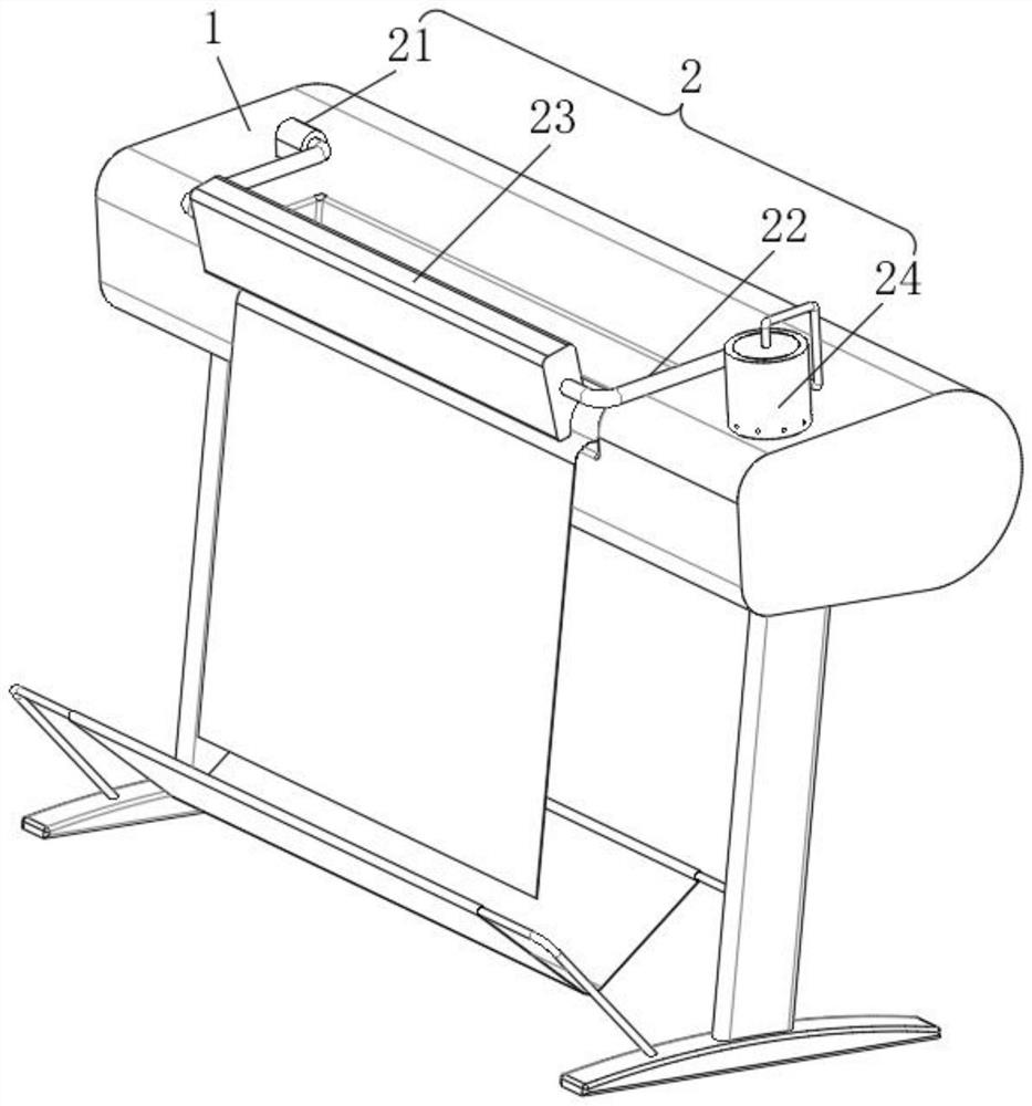
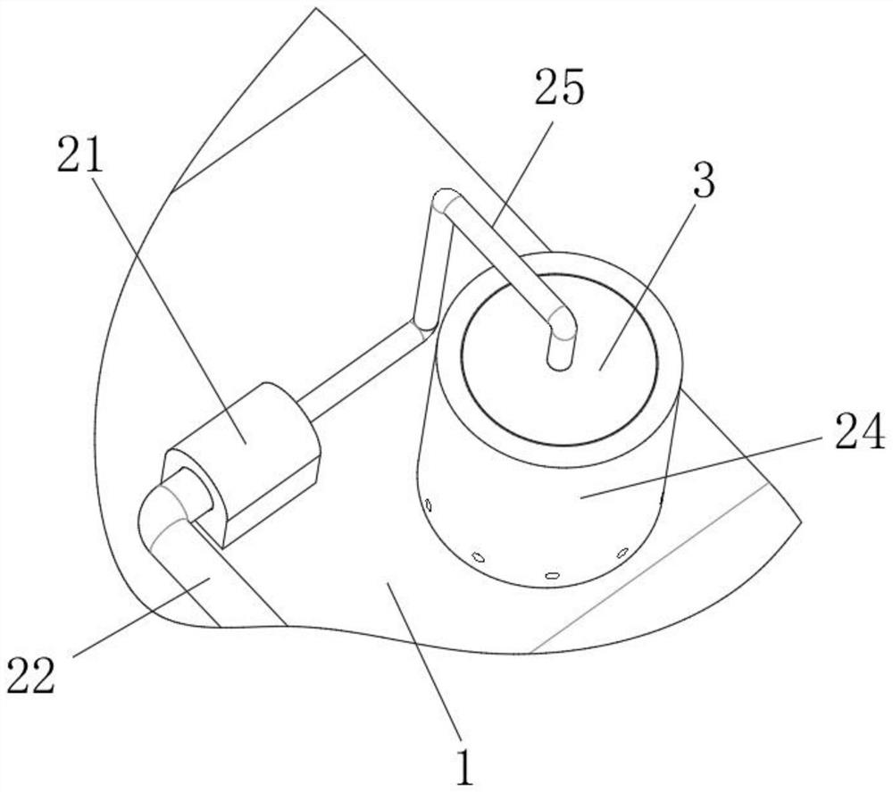
[0032] see Figure 1-3 , a computer image output device, comprising a drawing table 1, a canvas is arranged at the outlet of the drawing table 1, and a drying mechanism 2 for air-drying the ink on the surface of the canvas is arranged on the top of the drawing table 1, and the drying mechanism 2 includes an inflatable pipe fitting 24, and the inside of the inflatable pipe fitting 24 Insert the cleaning mechanism 3 that carries out water filtration to the exhaled airflow of the drying mechanism 2. The cleaning mechanism 3 includes an outer cover 33, and the top of the outer cover 33 is fixedly connected with an intercepting mechanism 4 that stops splashing water droplets in the cleaning mechanism 3.

[0033] The drying mechanism 2 includes two mounting bases 21, the inner sides of the mounting bases 21 are rotatably connected to the mounting frame 22, and the two mounting frames 22 are fixedly connected to the air outlet 23;

[0034] A connecting pipe 25 is installed between th...

Embodiment 2

[0038] see Figure 1-5 , a computer image output device, comprising a drawing table 1, a canvas is arranged at the outlet of the drawing table 1, and a drying mechanism 2 for air-drying the ink on the surface of the canvas is arranged on the top of the drawing table 1, and the drying mechanism 2 includes an inflatable pipe fitting 24, and the inside of the inflatable pipe fitting 24 Insert the cleaning mechanism 3 that carries out water filtration to the exhaled airflow of the drying mechanism 2. The cleaning mechanism 3 includes an outer cover 33, and the top of the outer cover 33 is fixedly connected with an intercepting mechanism 4 that stops splashing water droplets in the cleaning mechanism 3.

[0039] The drying mechanism 2 includes two mounting bases 21, the inner sides of the mounting bases 21 are rotatably connected to the mounting frame 22, and the two mounting frames 22 are fixedly connected to the air outlet 23;

[0040] A connecting pipe 25 is installed between the ...

Embodiment 3

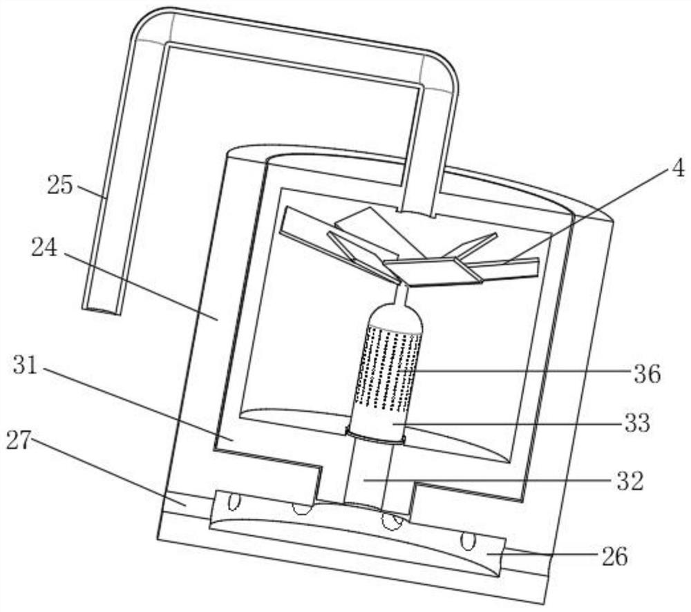
[0048] see figure 1 with Figure 4-6 , a computer image output device, comprising a drawing table 1, a canvas is arranged at the outlet of the drawing table 1, and a drying mechanism 2 for air-drying the ink on the surface of the canvas is arranged on the top of the drawing table 1, and the drying mechanism 2 includes an inflatable pipe fitting 24, and the inside of the inflatable pipe fitting 24 Insert the cleaning mechanism 3 that carries out water filtration to the exhaled airflow of the drying mechanism 2. The cleaning mechanism 3 includes an outer cover 33, and the top of the outer cover 33 is fixedly connected with an intercepting mechanism 4 that stops splashing water droplets in the cleaning mechanism 3.

[0049] The cleaning mechanism 3 includes a cleaning box 31 clamped on the inner side of the inflatable pipe 24. The bottom of the cleaning box 31 is provided with a bottom hole 32. The inner bottom wall of the cleaning box 31 is rotatably connected to the outer cover...


PUM


Abstract

The invention discloses a computer image output device. The device comprises a drawing table, wherein a canvas is arranged at an outlet of the drawing table, a drying mechanism for air-drying ink on the surface of the canvas is arranged at the top of the drawing table, and the drying mechanism comprises an inflation pipe fitting. According to the computer image output device, a cleaning mechanism is adopted to purify air blown out by the drying mechanism, the air firstly enters an inner cover through a bottom hole, and the inner cover is pushed by air pressure to move upwards along with more and more airflow entering the inner cover and the internal pressure exceeding the pulling limit of a pressure storage spring, so connecting holes of the inner cover and an outer cover are in butt joint, and high-pressure air accumulated in the inner cover is instantly ejected through the connecting holes; a fan continuously conveys air, the air flushes into a cleaning solution through the small connecting holes, dust in the air is mixed with the cleaning solution, and the air turns into bubbles which emerge from a water surface and are used by the drying mechanism; and therefore, the blown air has small influence on a drawn pattern, and the bright color of the pattern is ensured.

Description

technical field [0001] The invention relates to the technical field of plotters, in particular to a computer image output device. Background technique [0002] Computer image output devices include display devices and hard copy devices. The display device is a monitor, and hard copy devices include printers, plotters, drum scanners, and laser scanners. Intermediate results are expressed in the form of various media such as numbers, characters and images. [0003] Plotters are mostly used to draw various large-scale management charts and statistical charts, geodetic survey maps, architectural design drawings, etc. Its working principle is similar to that of a printer. It sprays ink on cloth rolls according to instructions to form various patterns. Because plotters are multi-purpose It is used for drawing color graphics, and the drawing area is large, so in the actual use process, the ink may not be dry in time, resulting in friction between the drawn graphics and foreign obj...

Claims


Application Information

Patent Timeline
IPC IPC(8): B01D47/02G06T11/20
CPCB01D47/021G06T11/206
Inventor 特列克别克·米沙
Owner 伊犁师范大学
Learn More