Gain equalization in c+l erbium-doped fiber amplifiers

A gain equalization, erbium-doped fiber technology, used in lasers, fiber transmission, laser components, etc., can solve problems such as more space beyond repeaters, loss shape resolution, etc.

Pending Publication Date: 2021-12-03
SUBCOM LLC
View PDF0 Cites 3 Cited by
  • Summary
  • Abstract
  • Description
  • Claims
  • Application Information

AI Technical Summary

Problems solved by technology

While these filters do not require optical isolators (such as SP-BGF) at both the filter input and output, the disadvantage of using S-BGF and LP-GF is perhaps their physical length, which may exceed practical limits and / or or ask for more space in the repeater
Furthermore, due to the limited loss shape resolution associated with TFF (and S-BGF and LP-GF) and the limited ability to track the steep slope of the gain curve, TFF (as well as S-BGF and LP-GF) may not be able to Sufficient accuracy in equalization and especially in broadband applications such as C+L EDFA

Method used


Image

  • Gain equalization in c+l erbium-doped fiber amplifiers
  • Gain equalization in c+l erbium-doped fiber amplifiers
  • Gain equalization in c+l erbium-doped fiber amplifiers

Examples


Embodiment Construction

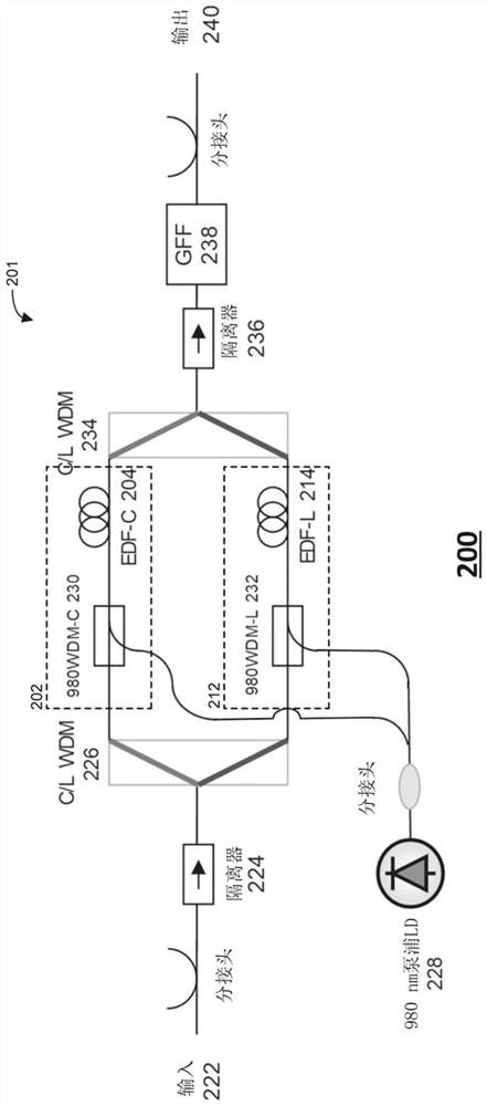
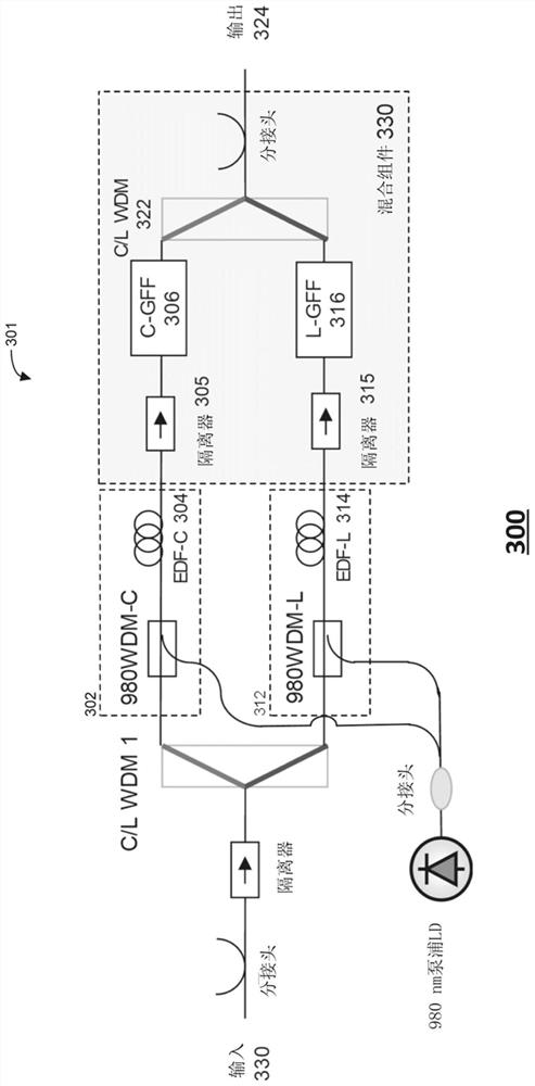
[0024] The present invention relates to improving at least gain equalization in C+L erbium-doped fiber amplifiers (EDFAs) for use in optical communication systems by at least separating the C-band and L-band amplification sections of the C+L EDFA according to various arrangements or flattened. According to one example, the C-band and L-band amplification sections of a C+L EDFA may be configured in a parallel arrangement (also referred to otherwise as a "parallel scheme"). According to another example, the C-band and L-band sections of a C+L EDFA may be configured in a serial arrangement (which may otherwise be referred to as a "serial scheme").

[0025] As will be described further below, at least two variations of the parallel scheme are possible. In a first variant, the C-band and L-band amplification sections of the C+L EDFA can share a common GFF. In a second variant, the C-band amplifying section may include and be coupled to a separate C-band GFF, and the L-band amplif...


PUM


Abstract

Techniques for improving gain equalization in C- and L-band (''C+L'') erbium-doped fiber amplifier (EDFAs) are provided. For example, the C- and L-band amplification sections of a C+L EDFA may be separated and configured in a parallel arrangement or a serial arrangement. For both the parallel and serial arrangements, the C- and L-band amplification sections may share a common gain flattening filter (GFF) or each amplification section may include and employ a separate GFF. Moreover, in some examples, an ''interstage'' L-band GFF may be located before or upstream of the L-band amplification section such that the L-band optical signal is gain-equalized or flattened prior to the L-band amplification section amplifying the L-band.

Description

technical field [0001] Embodiments of the present disclosure relate to the field of optical communication systems. More specifically, the present disclosure relates to improving at least gain equalization in C-band and L-band ("C+L") erbium-doped fiber amplifiers (EDFAs) used in optical communication systems. Background technique [0002] Long-range optical communication systems, such as undersea optical communication systems, typically suffer from signal attenuation caused by various factors including scattering, absorption, and bending. To compensate for attenuation, these long-distance systems may include a series of optical amplifiers spaced along the signal transmission path and configured to amplify or enhance the optical signal in a manner that allows reliable detection at the receiver. Depending on the length of the transmission path, the number of optical amplifiers positioned along the path may vary. [0003] An optical amplifier commonly used in long-distance op...

Claims


Application Information

Patent Timeline
Patent Type & Authority Applications(China)
IPC IPC(8): H04B10/25H04B10/69H04J14/02H01S3/067
CPCH04B10/25H04J14/0213H01S3/06766H01S3/0677H04B10/6931H04B10/2941H04B10/2916H04B10/2935G02B27/1006H01S3/0064H01S3/06758H01S3/0941H01S3/10023H01S3/1608H01S3/2391H01S2301/04
Inventor 德米特里·G·福萨阿列克谢·N·皮利佩特斯基马克西姆·A·布尔什泰安斯基格雷戈里·M·沃尔特
Owner SUBCOM LLC
Why Eureka
Try Eureka