Energy storage module and energy storage system

A technology for energy storage modules and cell packs, applied in battery pack components, electrical components, circuits, etc., to solve the problem that energy storage modules cannot perfectly adapt to new usage scenarios, and energy storage modules are not economical and feasible. Expansion, inability to meet market needs and other issues, to achieve the effect of taking into account reliability and security, improving group efficiency, and reducing development costs

Pending Publication Date: 2021-12-03
SHANGHAI AOWEI TECH DEV
View PDF0 Cites 1 Cited by
  • Summary
  • Abstract
  • Description
  • Claims
  • Application Information

AI Technical Summary

Problems solved by technology

However, with the expansion of new energy applications, the original standard energy storage modules cannot perfectly adapt to new usage scenarios and cannot meet the needs of the market
Because the existing energy storage modules are not economical and expandable, it is necessary to redesign the energy storage modules, such as adjusting the structure, etc., but the adjustment of the structure requires additional investment in production costs, which may not be able to meet the current requirements. Some market usage requirements may also cause a greater degree of waste of resources, etc.

Method used


Image

  • Energy storage module and energy storage system
  • Energy storage module and energy storage system
  • Energy storage module and energy storage system

Examples


Embodiment Construction

[0043] The following will clearly and completely describe the technical solutions in the embodiments of the application with reference to the drawings in the embodiments of the application. Apparently, the described embodiments are only some of the embodiments of the application, not all of them. Based on the embodiments in this application, all other embodiments obtained by persons of ordinary skill in the art without making creative efforts belong to the scope of protection of this application.

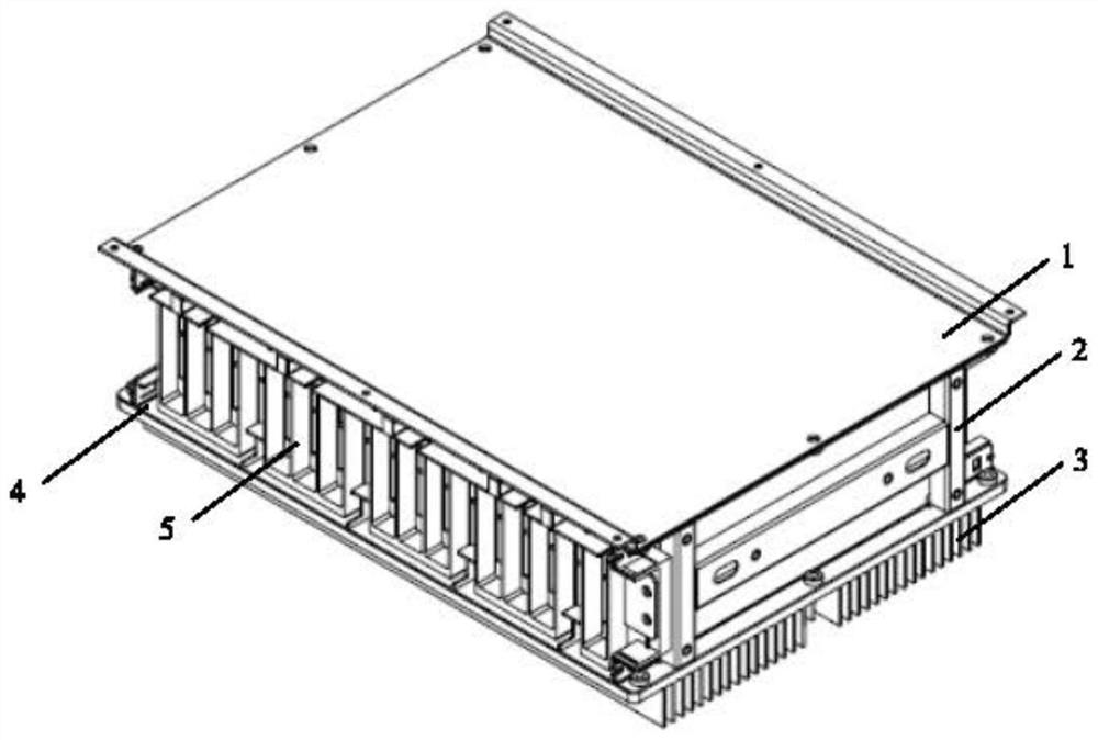
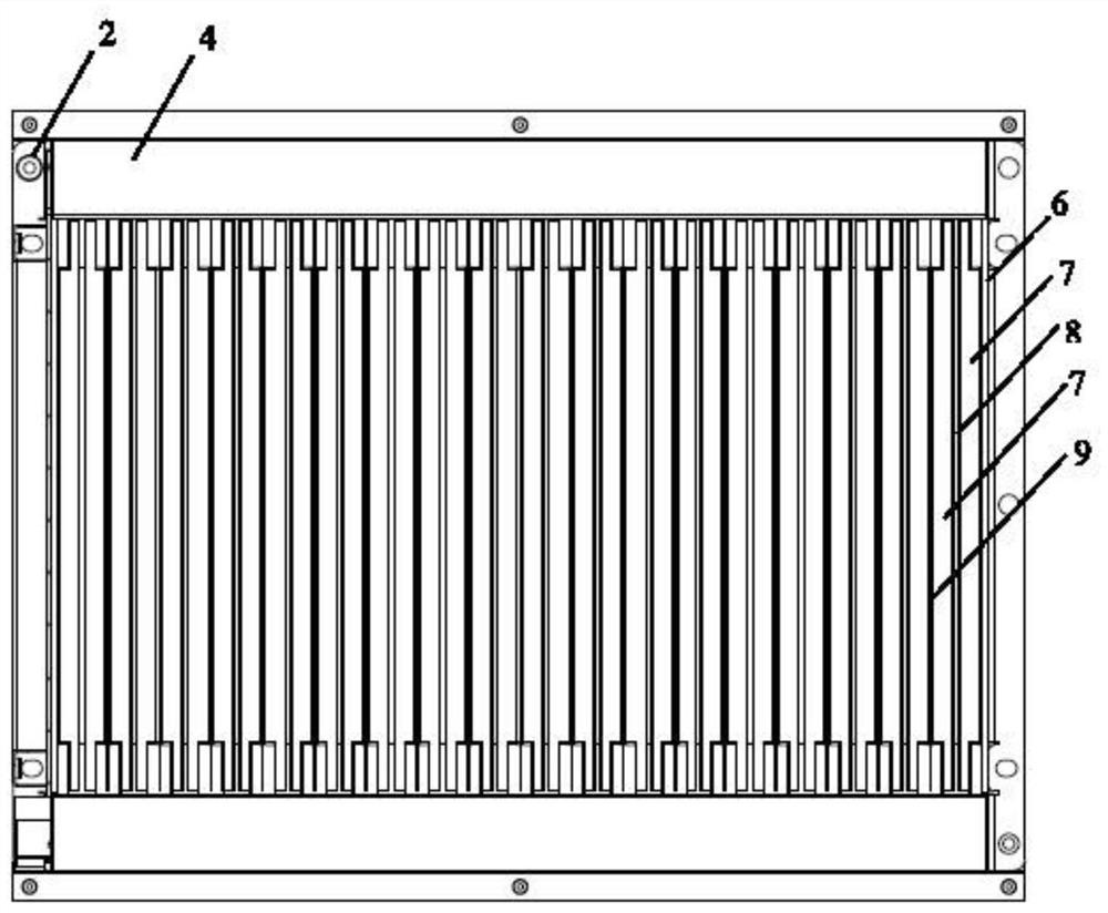
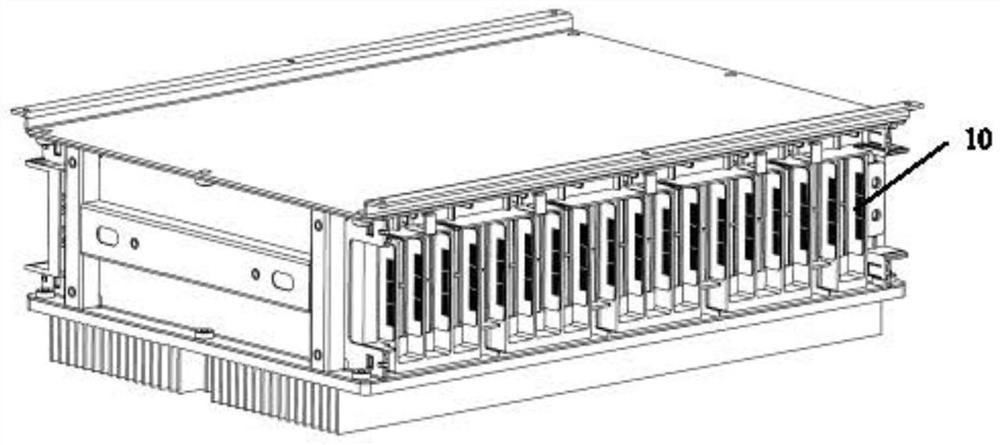
[0044] Such as Figure 1 to Figure 8 As shown, in one of the embodiments of the present application, an energy storage module includes: an end plate 2, an insulating plate 6 and a battery pack,

[0045] The end plates 2 are arranged at both ends of the energy storage module, and the insulating plates 6 are arranged inside the end plates 2, and at least one set of series-parallel The set of battery cores, the insulating plate 6 can also be replaced by an insulating material layer co...


PUM


Abstract

The invention discloses an energy storage module and an energy storage system. The energy storage module comprises end plates, insulating plates and a battery cell set, the end plates are arranged at the two ends of the energy storage module, the insulating plates are further arranged on the inner sides of the end plates, and at least one battery cell set arranged in series and in parallel is further arranged between the insulating plates; the insulating plates can also be replaced by insulating coating layers which are coated or injection-molded on the inner sides of the end plates; the battery cell set comprises battery cells, buffer layers, battery cells and flame-retardant layers, the buffer layers are arranged between the adjacent battery cells, and the flame-retardant layers are further arranged on the other sides of the battery cells. The energy storage system comprises energy storage modules, and the energy storage modules are installed according to the mode of at least one layer, at least one row and at least one column. Products of different sizes can be expanded, the development cost is reduced, the grouping efficiency of the energy storage module can be improved, the number of parts is reduced, the cost is reduced, and meanwhile reliability and safety are considered. The energy storage system can be assembled based on the energy storage modules so as to adapt to different application scenes.

Description

technical field [0001] The application belongs to the technical field of new energy, and specifically relates to an energy storage module and an energy storage system. Background technique [0002] Most of the existing energy storage module structures adopt standard module design to adapt to specific technical fields. However, with the expansion of new energy applications, the original standard energy storage modules cannot perfectly adapt to new usage scenarios and cannot meet the needs of the market. Because the existing energy storage modules are not economical and expandable, it is necessary to redesign the energy storage modules, such as adjusting the structure, etc., but the adjustment of the structure requires additional investment in production costs, which may not be able to meet the current requirements. Some market usage requirements may also cause a greater degree of waste of resources. Contents of the invention [0003] In view of the shortcomings or deficie...

Claims


Application Information

Patent Timeline
IPC IPC(8): H01M50/204H01M50/251H01M50/227H01M50/242H01M50/289H01M50/293H01M50/505
CPCH01M50/204H01M50/251H01M50/227H01M50/242H01M50/289H01M50/293H01M50/505Y02E60/10
Inventor 解凌峰严嵘龚正大章锦钱辉华黎
Owner SHANGHAI AOWEI TECH DEV
Why Eureka
Try Eureka