Sliding door lock

A lock and locking technology, applied in the field of locks, to achieve the effect of improving safety, avoiding derailment, and simplifying complexity

Active Publication Date: 2021-11-30
DOOR & WINDOW HARDWARE
View PDF8 Cites 0 Cited by
  • Summary
  • Abstract
  • Description
  • Claims
  • Application Information

AI Technical Summary

Problems solved by technology

[0007] Therefore, in view of the problems in the structure and use of the existing sliding door locks, the inventor has developed an improved existing sliding door lock through continuous testing and research. defective invention

Method used


Image

  • Sliding door lock
  • Sliding door lock
  • Sliding door lock

Examples


Embodiment Construction

[0030] In the following, the technical means adopted by the present invention to achieve the intended purpose of the invention will be further described in conjunction with the accompanying drawings and preferred embodiments of the present invention.

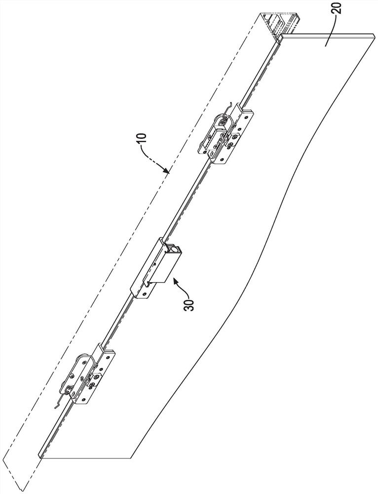
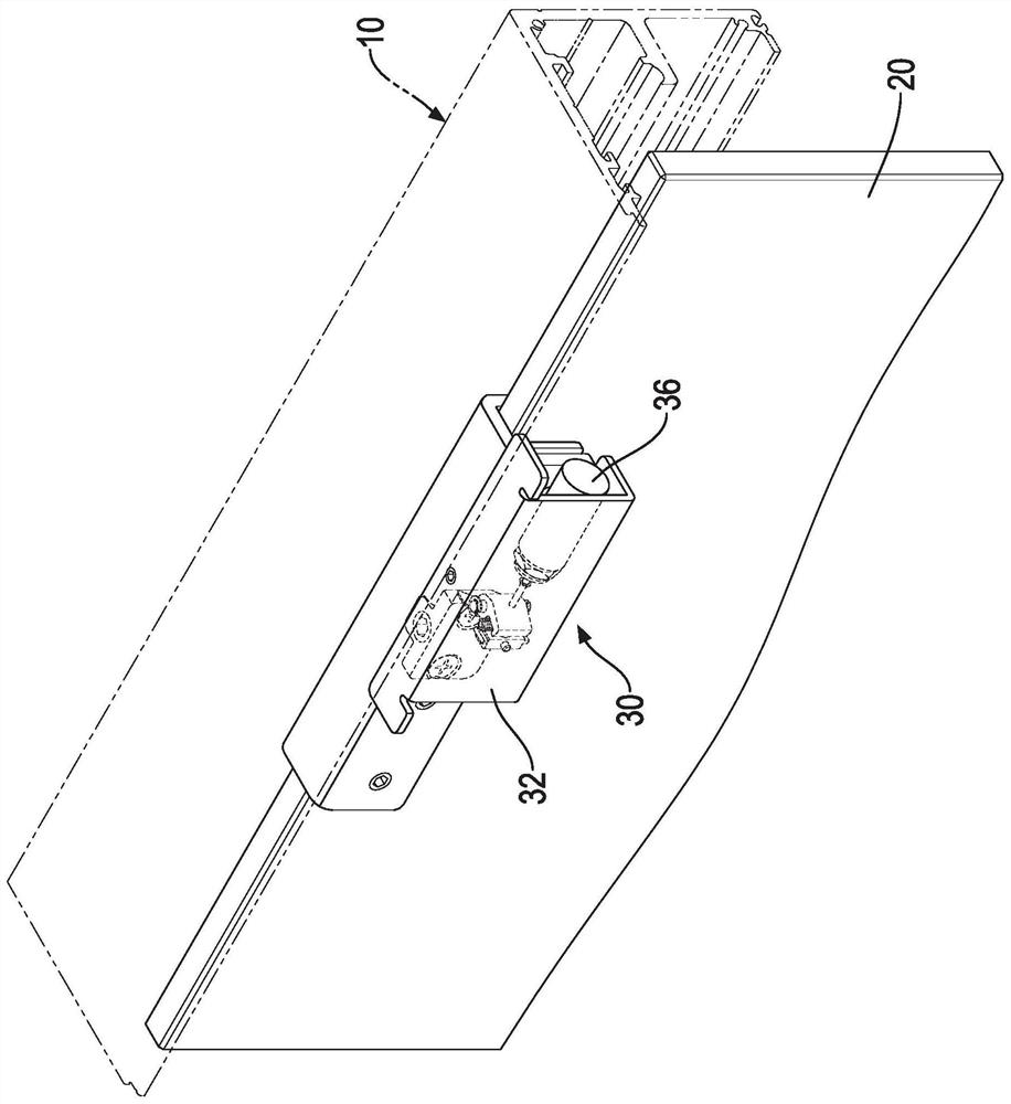
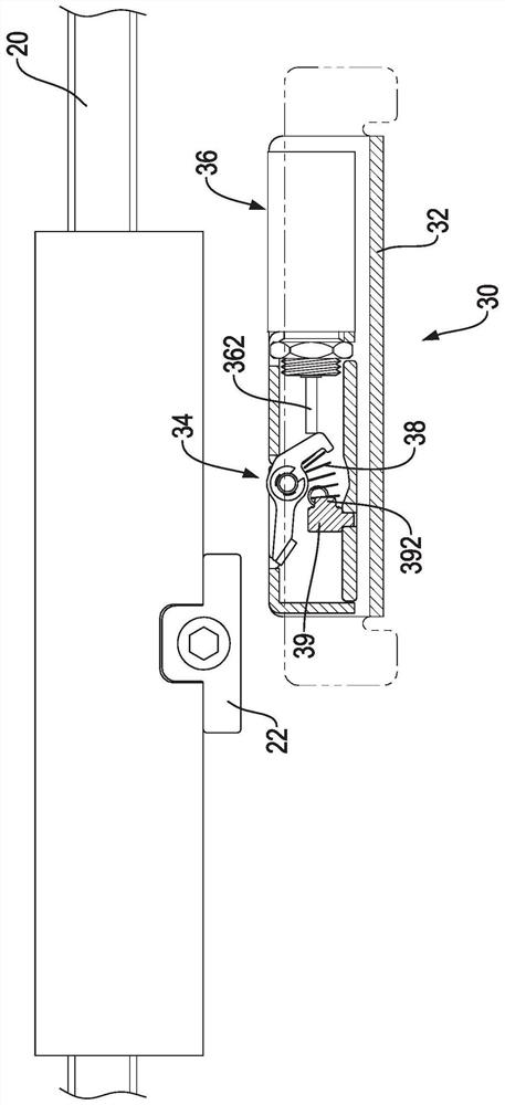
[0031] The invention relates to a lockset for the sliding door, please refer to Figure 1 to Figure 3 As can be seen from the figure, the sliding door used by the lockset of the present invention mainly includes a track 10 and at least one door panel 20. The track 10 can be fixed on the door frame, and a power device such as a motor and a belt or belt can be arranged in the track 10. Roller and other transmission devices, so that the sliding door is an electric sliding door. The provided power device and transmission device make the door panel 20 automatically move relative to the track 10 to open or close the sliding door, wherein the track 10 can be arranged above the door panel 20 .

[0032] The lock 30 of the present invent...


PUM


Abstract

The invention relates to a sliding door lock. The lock comprises a base, a clamping and blocking part, a driving unit, a returning unit and a locking block, wherein the base is connected and fixed to a rail of a sliding door; the clamping and blocking part can be arranged on the base in a pivoting mode relative to the base and is provided with an unlocking position and a locking position protruding out of the outer side of the base; when the clamping and blocking part is located at the locking position, a locking surface which is in contact with a door plate is formed; the driving unit is arranged on the base and is connected to the clamping and blocking part so as to provide force for enabling the clamping and blocking part to move from the unlocking position to the locking position; the returning unit is arranged in the base and is connected to the clamping and blocking part so as to provide force for enabling the clamping and blocking part to return from the locking position to the unlocking position; and the locking block is used for fixed to the door plate and selectively abuts against the locking surface of the clamping and blocking part when the clamping and blocking part is located at the locking position, so that the sliding door lock which is simple in structure and is capable of improving the usage safety is formed.

Description

technical field [0001] The present invention relates to a lock, especially a lock for sliding doors. Background technique [0002] Existing sliding doors, electric or manual, generally include a track and at least one door panel that can move along the track. In order to enable the existing sliding door to be locked and prevent other people from entering arbitrarily, there will be a separate lock on the existing door panel. Set a lock to lock the sliding door, as shown in German Patent No. 10 2016 217 664 (hereinafter referred to as the reference), the lock of the reference mainly has a locking device and a driver, and the locking device has a latch And a self-recovery force makes the latch move to an unlocked position, and the latch is in the operable locked position by overcoming the self-recovery force in the direction actuated by the driver, so that when the latch is in the locked position, it can be locked Control the sliding door to prevent other people from opening t...

Claims


Application Information

Patent Timeline
Patent Type & Authority Applications(China)
IPC IPC(8): E05B65/08E05B47/00E05B15/10
CPCE05B65/0811E05B47/0012E05B47/023E05B15/10
Inventor 张尉弘林松辉
Owner DOOR & WINDOW HARDWARE
Why Eureka
Try Eureka