
Novel lens honeycomb panel lamp

A honeycomb and panel technology, applied in the field of optical lens honeycomb panel lights, can solve the problems of single installation structure, inconvenient installation of panel lights, etc., and achieve the effect of improving production efficiency and improving the scope of application

Pending Publication Date: 2021-11-23
刘美阳
View PDF0 Cites 0 Cited by
  • Summary
  • Abstract
  • Description
  • Claims
  • Application Information

AI Technical Summary

Problems solved by technology

[0003] The purpose of the present invention is to provide a new type of optical lens honeycomb panel light, which can be installed or installed according to the installation needs of the panel, and the assembly of the panel light does not require screws, and the advantages of convenient installation solve the problem that the panel light can only be single Concealed installation through the cooperation of torsion springs, or single surface installation through the cooperation of screws, etc., the installation structure is single, and it is not convenient to install according to the installation requirements of the panel light during installation

Method used


Image

  • Novel lens honeycomb panel lamp
  • Novel lens honeycomb panel lamp
  • Novel lens honeycomb panel lamp

Examples


Embodiment 2

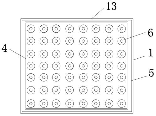
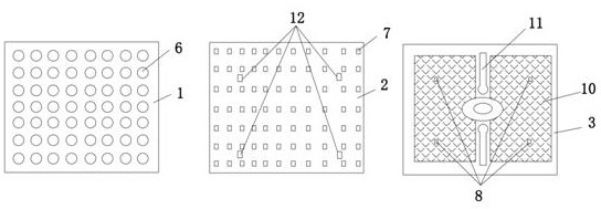
[0025] see Figure 2-3 , a new type of optical lens honeycomb panel light, comprising an optical lens honeycomb panel 1, a light source plate 2 and a heat dissipation back cover 3, the inner side of the optical lens honeycomb panel 1 is integrally provided with a card edge 4, and the card edge 4 is set There is a card slot 5 installed on the cooling back cover 3;

[0026] The installation end of the optical lens honeycomb panel 1 is integrally provided with small particle lenses 6 arranged in order, and the end surface of the light source board 2 is provided with lamp beads 7, and the lamp beads 7 on the light source board 2 are set corresponding to the small particle lenses 6. Inside the optical lens honeycomb panel 1, the installation end of the heat dissipation back cover 3 is provided with a buckle 8, and the corresponding buckle 8 on the light source board 2 is provided with a hole 12 that is fastened with the buckle 8. After the heat dissipation, The buckle 8 provided o...


PUM


Abstract

The invention discloses a novel optical lens honeycomb panel lamp which comprises an optical lens honeycomb panel, a light source plate and a heat dissipation rear cover, the optical lens honeycomb panel is a honeycomb reflector composed of light-transmitting glass, an outer frame and small optical lenses, the optical angles of 0-360 degrees are arranged in the lenses, and the optical lens honeycomb panel is formed in a three-in-one mode. A clamping groove is formed in the inner side of the mounting end of the optical lens honeycomb panel, and a clamping groove for mounting the heat dissipation rear cover is formed through the clamping edge. A small-particle lens is arranged at the inner mounting end of the optical lens honeycomb panel; a buckle of the heat dissipation rear cover corresponds to a hole site of the light source plate and is fixedly clamped with the hole site of the light source plate through the buckle of the heat dissipation rear cover; and the heat dissipation rear cover is provided with a hole position matched with the surface-mounted rear cover. The novel optical lens honeycomb panel lamp integrates high lumen and high luminous efficiency with the optical angle ranging from 0 degree to 360 degrees, has the function of open installation or concealed installation according to the installation requirement of the honeycomb panel lamp, and has the advantages that the panel lamp light source plate and the heat dissipation rear cover are assembled together without screws, and installation is convenient and fast.

Description

technical field [0001] The invention relates to the technical field of panel lights, in particular to a novel optical lens honeycomb panel light. Background technique [0002] The panel light is a high-end indoor lighting fixture. Its outer frame is made of aluminum alloy / plastic, and the light source is LED. The design of the whole lamp is beautiful and simple, and the atmosphere is luxurious. , At present, for the installation of the panel light, it can only be concealed by a single torsion spring, or exposed by a single screw, etc. The installation structure is single, and it is not convenient to install according to the installation requirements of the panel light during installation. Contents of the invention [0003] The purpose of the present invention is to provide a new type of optical lens honeycomb panel light, which can be installed or installed according to the installation needs of the panel, and the assembly of the panel light does not require screws, and th...

Claims


Application Information

Patent Timeline
IPC IPC(8): F21S8/00F21S8/02F21V15/015F21V21/00F21Y115/10
CPCF21S8/00F21S8/026F21V15/015F21V21/00F21Y2115/10
Inventor 刘美阳
Owner 刘美阳
Learn More