Dust box structure applied to floor mopping robot and capable of preventing garbage from falling
A sweeping robot and sweeping machine technology, applied in the field of sweeping robots, can solve problems such as garbage falling from the opening of the open dust box
- Summary
- Abstract
- Description
- Claims
- Application Information
AI Technical Summary
Problems solved by technology
Method used
Image

Examples
Embodiment 1
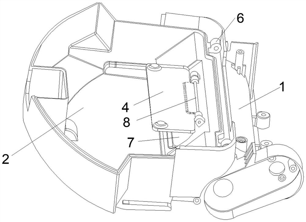
[0048] The embodiment of the present invention provides a dust box structure for anti-garbage falling floor sweeping robot, please refer to figure 1 , the present invention provides a technical solution: comprising: sweeper dust box lower cover 2, dust baffle 4, the side wall of the sweeper dust box lower cover 2 is provided with a dust box garbage inlet 7, the dust baffle 4 Connected with the first rotating rod 8, through the first rotating rod 8 and the inner wall of the dust box lower cover 2 of the sweeper, the dust baffle 4 (preferably, the rear side of the dust baffle 4 is fixed with a support plate 11 ( figure 1 The dotted line in the middle shows that the side and the above-mentioned rear side of the dust baffle near the dust box garbage inlet 7 are arranged, and the support plate 11 is fixedly connected with the first rotating rod 8) for closing or opening the dust box garbage inlet 7.
[0049] The beneficial effect of above-mentioned technical scheme is:
[0050] Th...
Embodiment 2
[0052] On the basis of Example 1, please refer to Figure 2-3 , the sweeping machine tooth brushing box 1, the sweeping machine tooth brushing box 1 and the sweeper dust box lower cover 2 are rotationally connected by a first connecting column 6 .
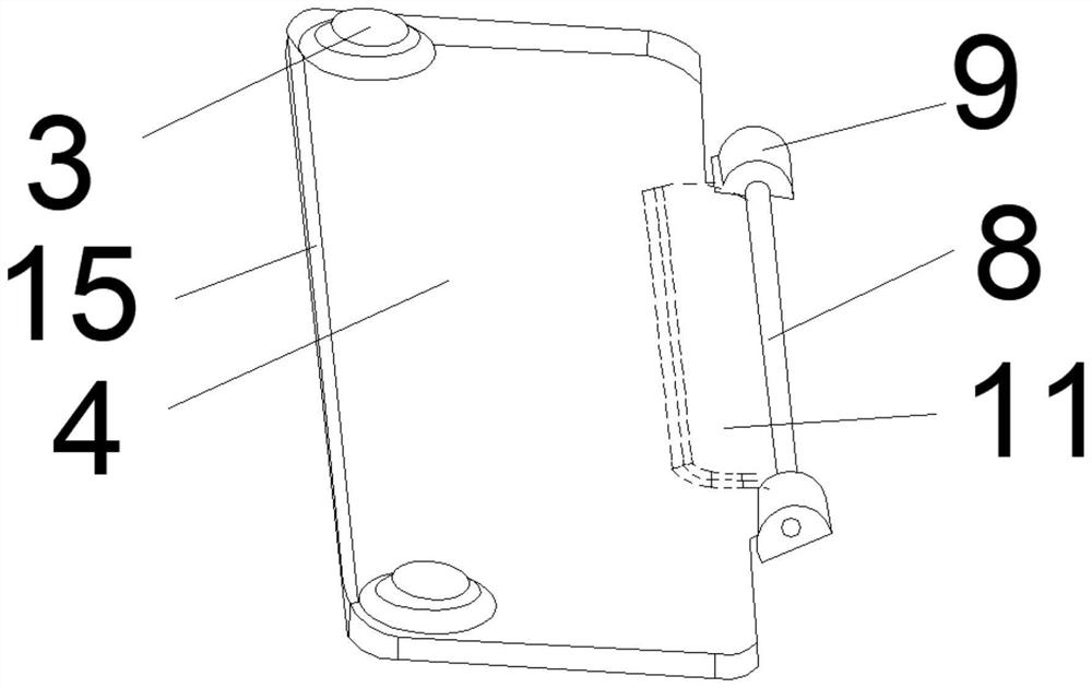
[0053] The right side wall of the dust box lower cover 2 of the sweeping machine is provided with a dust box garbage inlet 7, and the dust baffle 4 is connected with: a first latch 3, a first rotating rod 8, a first connecting block 9, and a magnet 15. The dust baffle 4 is symmetrically fixedly connected with two groups of first bolts 3 front and back, and the right side wall of the dust baffle 4 is fixedly connected with two groups of first connecting blocks 9 symmetrically front and back, and the first connecting blocks 9 of the two groups are fixedly connected front and rear symmetrically. The first rotating rod 8 is connected between the blocks 9;
[0054] The right side wall of the dust box lower cover 2 of the sweeper is loc...
Embodiment 3
[0060] On the basis of any one of the embodiments 1-2, please refer to Figure 4 , the sweeping machine tooth brushing box 1 includes: a first mounting plate 13, a second mounting plate 14, the sweeping machine tooth brushing box 1 is plugged into the first mounting plate 13 and the second mounting plate 14 Both sides of the right side wall of the dust box lower cover 2 of the sweeper.
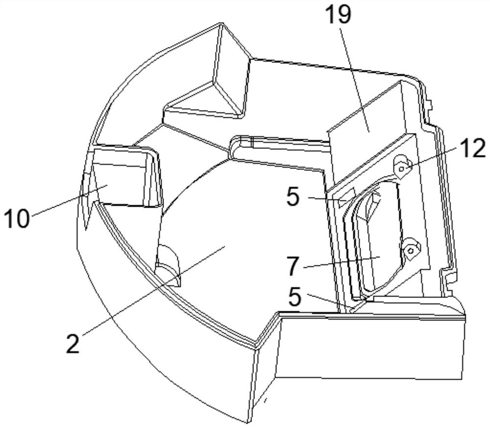
[0061] The sweeping machine roller tooth box 1 is fixedly connected with the first installation block 16, the first installation block 16 is a concave cavity structure, two groups of through holes 17 are opened on the rear wall of the first installation block 16, the A side of the upper end of the first mounting block 16 close to the second mounting plate 14 is fixedly connected with several clamping blocks 18 with a trapezoidal cross-section.
[0062] The inner wall on the right side of the dust box lower cover 2 of the sweeper is set as a slope structure 19 .
[0063] The beneficial effect...
PUM
| Property | Measurement | Unit |
|---|---|---|
| Yield strength | aaaaa | aaaaa |
Abstract
Description
Claims
Application Information
 - R&D
- Intellectual Property
- Life Sciences
- Materials
- Tech Scout
- Unparalleled Data Quality
- Higher Quality Content
- 60% Fewer Hallucinations
Browse by: Latest US Patents, China's latest patents, Technical Efficacy Thesaurus, Application Domain, Technology Topic, Popular Technical Reports.
© 2025 PatSnap. All rights reserved.Legal|Privacy policy|Modern Slavery Act Transparency Statement|Sitemap|About US| Contact US: help@patsnap.com