Conductive contact structure and relay
A technology of conductive contact and static contact, which is applied in the direction of electromagnetic relay, relay, detailed information of electromagnetic relay, etc., can solve the problems affecting the closing effect, etc., and achieve the effect of simple structure, easy realization and stable connection
- Summary
- Abstract
- Description
- Claims
- Application Information
AI Technical Summary
Problems solved by technology
Method used
Image

Examples
Embodiment 1
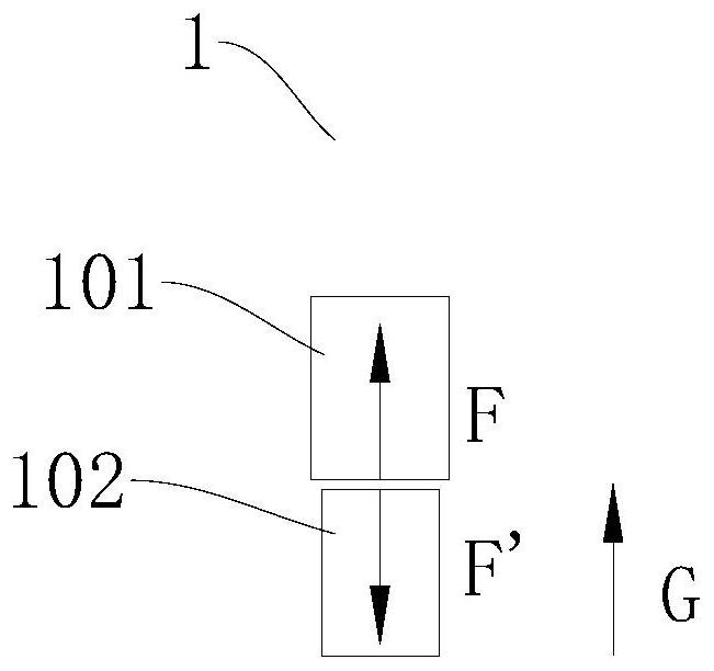
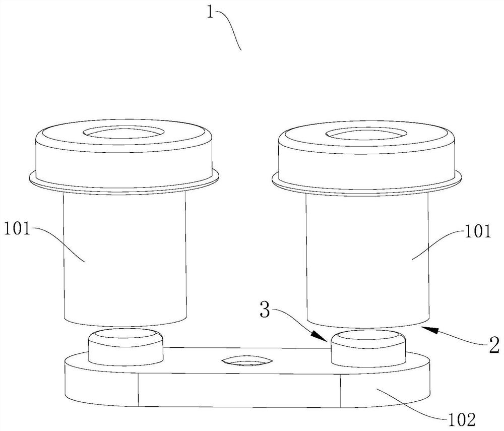
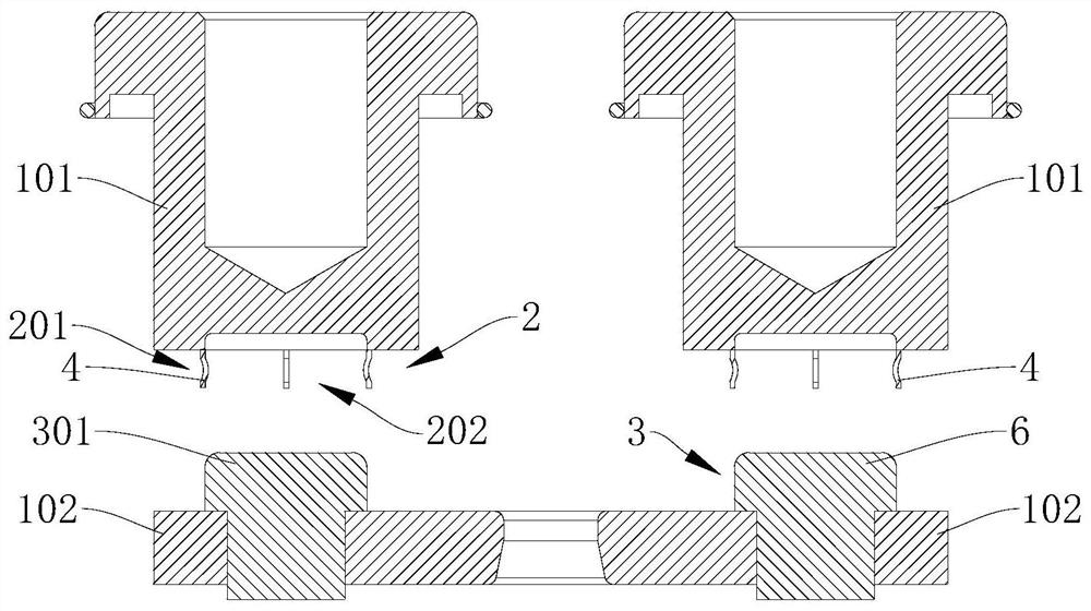
[0051] refer to Figure 2-7 , the present invention discloses a conductive contact structure 1, including a static contact 101 and a moving contact 102, the moving contact 102 is movable relative to the static contact 101; wherein, one of the static contact 101 and the moving contact 102 A socket structure 2 is provided, and a plug structure 3 is provided on the other. At least one of the socket structure 2 and the plug structure 3 is an elastic structure, so that the plug structure 3 can be inserted into the socket structure 2, and the surfaces of the two are against each other. connected and electrically connected, and the normal direction at the abutting surface of the two is not collinear with the direction in which the plug structure 3 and the socket structure 2 are inserted into each other (for the convenience of description, hereinafter referred to as the insertion direction), so that the static The direction of the repulsive force generated when the contact 101 and the...
Embodiment 2
[0074] This embodiment discloses another conductive contact structure 1, which is based on Embodiment 2 and differs from Embodiment 2 only in that:
[0075] refer to Figure 8-14 , the socket structure 2 also includes a rigid connection body 6, the connection body 6 is provided with an insertion groove 601, the first elastic member 201 is arranged on the inner wall of the insertion groove 601, and the first elastic member 201 is arranged on a connection The advantage of the insertion groove 601 of the body 6 is that it can facilitate the positioning of the first elastic member 201, so that the first elastic member 201 is excessively expanded and deformed to interfere with other components, and it can also connect the plug structure 3 with the second elastic member. The arc that may be generated when an elastic member 201 is in contact is limited in the insertion groove 601, so as to avoid the impact of the arc on other components.
[0076] As a possible implementation, the in...
Embodiment 3
[0092] This embodiment discloses another conductive contact structure 1. Based on Embodiment 1 or Embodiment 2, the differences between this embodiment and Embodiment 1 or Embodiment 2 are:
[0093] refer to Figure 15 , in this embodiment, the plug structure 3 is an elastic structure, the socket structure 2 is a rigid structure, the socket structure 2 includes a rigid connection body 6, and the connection body 6 is provided with an insertion groove 601 for plugging the plug structure 3 .
[0094] Thus, the plug structure 3 of this embodiment is inserted into the insertion groove 601 , and the plug structure 3 is deformed so that the plug structure 3 can be inserted into the socket structure 2 and abut against the inner wall thereof to be electrically connected.
[0095] As a possible implementation, the plug structure 3 includes a second elastic member 7, and the second elastic member 7 forms a plug body 301 that can expand or contract. The plug body 301 is inserted into the...
PUM
 Abstract
Description
Claims
Application Information
 - R&D
- Intellectual Property
- Life Sciences
- Materials
- Tech Scout
- Unparalleled Data Quality
- Higher Quality Content
- 60% Fewer Hallucinations
Browse by: Latest US Patents, China's latest patents, Technical Efficacy Thesaurus, Application Domain, Technology Topic, Popular Technical Reports.
© 2025 PatSnap. All rights reserved.Legal|Privacy policy|Modern Slavery Act Transparency Statement|Sitemap|About US| Contact US: help@patsnap.com